In the previous chapter, we created some fairly sophisticated behavior using expressions. Setting up such systems takes some time, though, and if you build something that you like, you may wish to use it again later on, either for its own sake or as a component for something even more complex. Fusion allows you to create macros, which are collections of tools that can have customized controls and be reused. The Nuke equivalent is a gizmo. After Effects doesn't have a direct analogue, although both presets and templates fill something of the same purpose.
Fair warning: This chapter is going to get a little technical, and we'll even be writing a little code. I promise it won't hurt much, and when we're done, you'll be that much more valuable as a compositor!
Spot Remover Macro
Let's start with something simple. In the Expressions chapter, I demonstrated how to remove small blemishes using a pair of ErodeDilate nodes. Since I make that set of nodes frequently, it seems like a good candidate for a macro. Start by setting up the two Erode Dilate nodes and the expression just like I did in that demonstration. There are two mask inputs, but we will only want to have one visible in the macro, so also make a Bitmap node and connect it to both mask inputs on the ErodeDilates.
Before we move on, notice the odd positions I have given my nodes above. When creating a macro the order of the inputs and the controls is important, and they'll appear in the order that they appear in the flow: Top-to-bottom, then left-to-right. By putting ErodeDilate1 a little higher and further to the left than the other nodes, I can make sure that it appears first in the list, and that its controls take priority over the others. If the Bitmap were to be positioned above the other two nodes, then its input would get the gold Background arrow. The more elaborate macros we set up later in this chapter will rely on this quirk even more heavily.
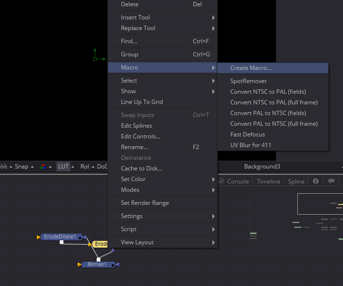
Select all three nodes, right-click one of them, and choose Macro > Create Macro… from the context menu. The Macro Editor window appears. This is where you will set up the control panel for your new tool. First, give it a name. I'm calling mine SpotRemover. A tool cannot have any spaces or hyphens in its name, and it cannot begin with a numeral.
Each tool you had selected appears, with all of its controls, in the Macro Editor window. The Export column determines what controls will be visible to the user. Start by determining your input and outputs. ErodeDilate1 has the Input I want, so I open it and check it off. Notice how the name of the node changes color as soon as you check something in it—that shows you at a glance which nodes have exposed controls. In Fusion 7 it turns blue, which was much easier to see than this slightly darker gray that Fusion 8 uses. Fusion will activate every disconnected Output it finds, so in a complex macro it's a good idea to scan down to see if there's a node with controls activated that you don't need.
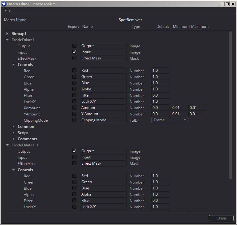 The Output comes from ErodeDilate1_1 (or ErodeDilate2 if you didn't copy-and-paste the node like I did). Here you can see my Editor with the Input and Output selected.
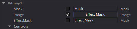
Finally, we need to set up the Effect mask input. That will come from the Bitmap node, but what we actually want to expose is the gold Image input. We'll rename it Effect Mask, though. Fusion doesn't care that there's already an Effect Mask input (there are actually three of them—one for each tool) because this exposed input will be attached to the entire macro, not to the Bitmap node.
That takes care of the inputs. The next thing we need to worry about is the control panel itself. Since this is our very first macro, we'll keep things simple and not provide the option to unlink X and Y, like a regular ErodeDilate can do. We'll just provide a single slider. In ErodeDilate1, the control XAmount is the one we want; check it. As long as LockXY is unchecked, XAmount controls both X and Y, which is why its name is simply "Amount." Leave everything else as it is and click the "Close" button in the lower right corner. Fusion asks if you want to save changes to MacroTool1. Click "Yes," and a file browser will appear, already pointed to your Macros directory and with the name you chose pre-filled in the file name field. Assuming that's where you want to put it and that's the name you want to give it, click "Save."
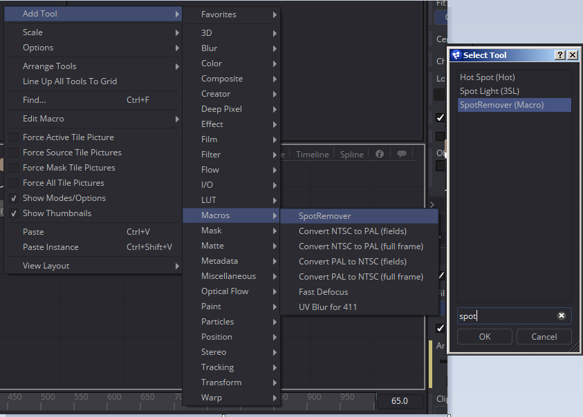 The new macro immediately shows up in the Add Tool and Select Tool dialogues, ready for use.
Unfortunately, there is a problem with it. Although we named the Bitmap's input "Effect Mask," Fusion doesn't actually treat it as such. It's been given a green input triangle, and its scripting name is MainInput2 instead of EffectMask. Likewise, the main input is called MainInput1 instead of simply Input. And the Amount input is labeled as we expected, but its scripting name is Input1. This isn't really a big deal for a quick tool you make for yourself, but if you want to share the Macro with others, it's nice to make sure its inputs and outputs are standardized to some degree.
The way to fix it is to load the macro in a plain-text editor. Don't use a full-blown word processor for this—those tend to add hidden control characters like ¶ whenever you hit Return. You can use Notepad in Windows or TextEdit on the Mac will do, but if you have a script editor like SciTE or Notepad++, that is even better. Some versions of Fusion (7.7, for instance) even include SciTE in their installation; it can be launched using Script > Edit > New Script… Windows' Notepad doesn't read Fusion's carriage returns, so it can be difficult to read the file. I'm going to use Notepad++ because I don't hate myself.
Finding the new macro file might be a little tricky. Although there is a Macros folder in Fusion's install directory, that's probably not where the macro went. Remember those Path Maps I mentioned in the previous chapter? One of them is for Macros, and by default it points to UserPaths:Macros. UserPaths itself is another Path Map that points to UserData:, AllData:, and Fusion:. And each of those is another Path Map. Fusion uses the first valid location it finds if there's a list, so we tunnel a little deeper to find out where UserData is pointing, and that will take us to where the macro is stored.
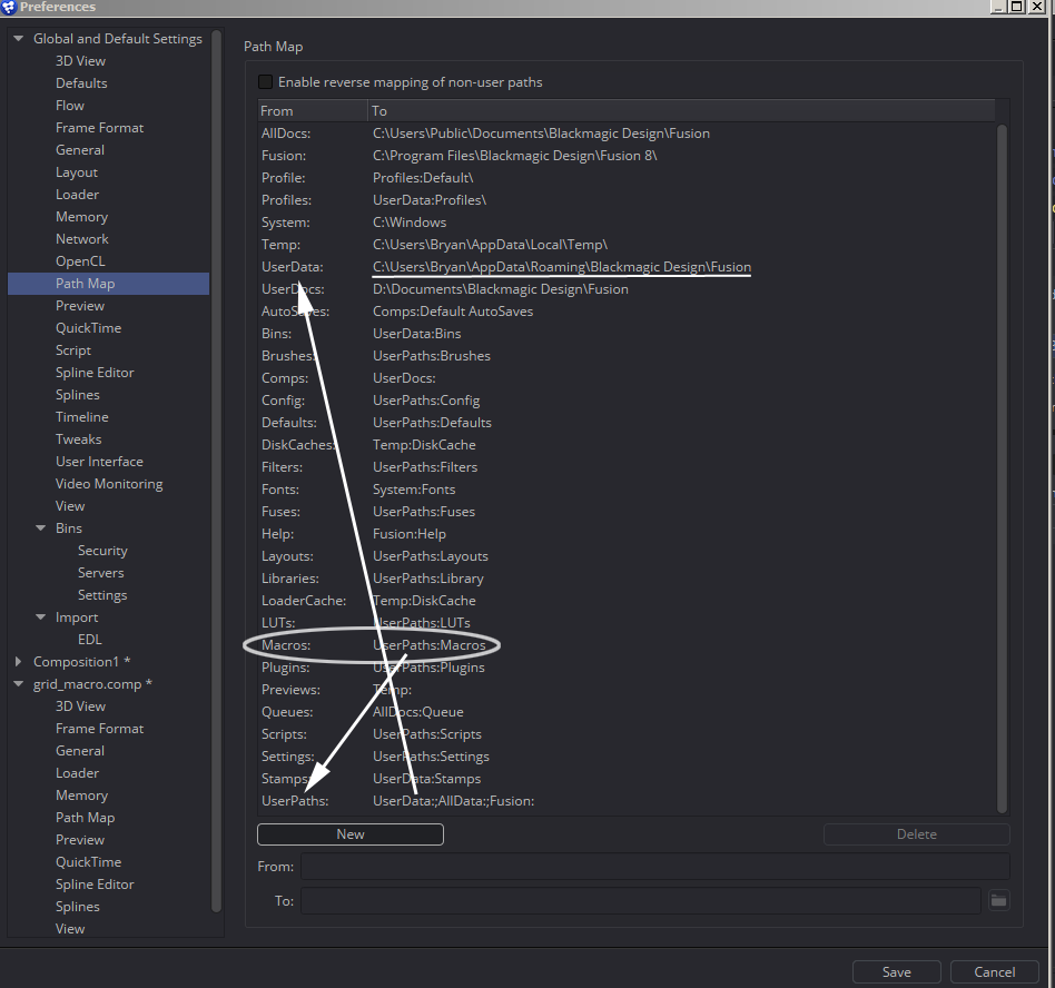
To top it off, in a typical Windows installation, the AppData folder is hidden, making it even harder to find! If that's the case for you, look up how to show hidden folders in your operating system on the Internet. For sanity's sake, you might consider changing the UserPaths map to point to UserDocs instead of UserData. That will put everything in your Documents folder instead of a hidden secret location. Or you could set up a map to a folder of your choice elsewhere.
Anyway, once you've found the elusive Macros folder, load up your macro in the text editor. Its extension is ".setting" so you'll have to set your filename filter to All Files (*.*) in order to see it in the file browser.
If you insist on using Notepad, you will get this mess:
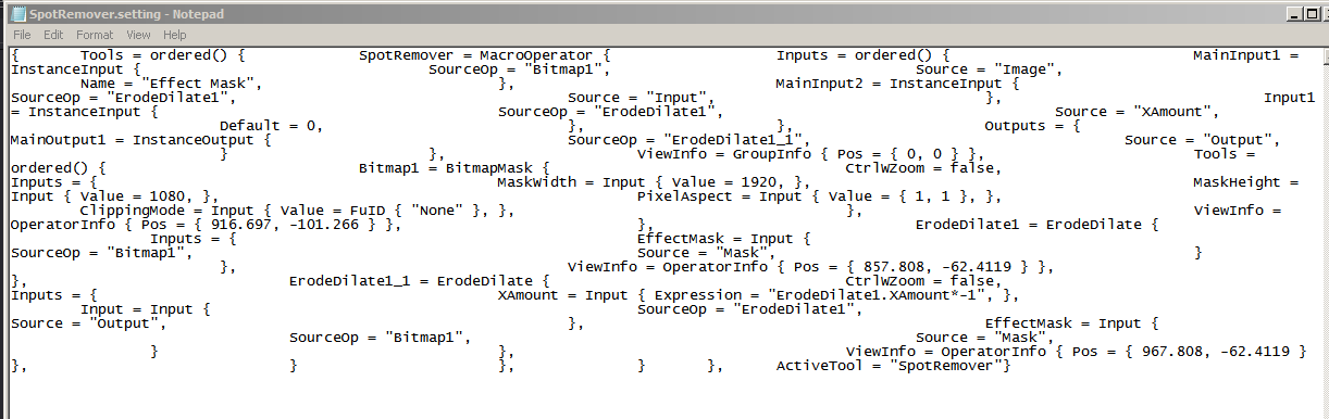
It's not Fusion's fault, though. It shows up great in Notepad++.
Using a text editor, we can modify several aspects of the macro. In this case, we want to change "MainInput2," which is supposed to be the Effect Mask, to "EffectMask" and "MainInput1" to simply "Input." Then we'll change "Input1" to "Amount" and "MainOutput1" to "Output."
Once those changes have been made, save the file and return to Fusion. Add a new SpotRemover to the flow and notice the changes. The effect mask input is now named EffectMask and has a blue icon, and the input is now Input.
The order of the Inputs in the text file is important. The main Input needs to be first in the list, and the controls need to be in the order you want them to appear in the Control Panel.
It isn't always necessary to create a perfectly-formed macro. If you're just making it for yourself to save some time, it's not critical that the inputs are colored correctly or have good names. If you're going to share it with the world, though, it's nice to make the tool as similar to standard tools as you can. There are a few more things that could be done here to make it even better. We could set up the Blend control and the other features of the Common tab, and we could expose the Filter method and Clipping Mode. We'll look into doing all of that for our next tool.
The Color Difference Keyer
As promised in the previous chapters on Expressions and Keying, we'll use the information we learned there about the Custom Tool and combine it with our new skill at creating Macros in order to create a superior keying tool that operates similarly to the Keylight plug-in, which is no longer available for Fusion.
In The Art and Science of Digital Compositing, second edition, Ron Brinkmann offers a description of the color difference method for extracting a matte from chroma-key footage, based on an optical process developed in the 1950's. His description of the method begins on page 214 of the book. The tool we develop here will be based on Brinkmann's description. The finished tool will be capable of pulling a matte that preserves fine, translucent detail, suppressing spill from the greenscreen, and combining the despilled footage with a background. The tool will be specific to greenscreens, but it can be extended to handle blue and redscreens.
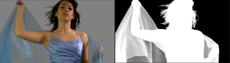
The first step in the keying process is to suppress the color of the green background. We'll start with one of those problematic images from the Keying chapter:
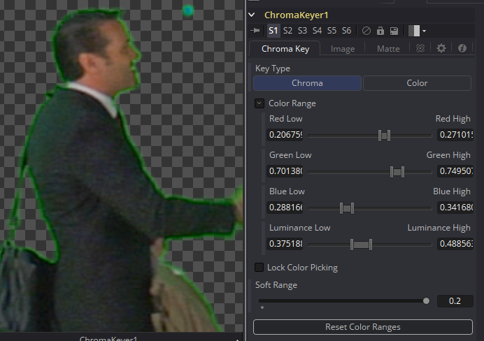
Remember the lousy results we had with the Chroma Keyer on this guy? I think we can do better! (But oh, how I wish we'd set the cameras up properly—that oversharpening kills me!) Load up the plate from chapter 4 and find a frame that has some nice hair detail, and perhaps some motion blur. The other keyers have a hard time with those features, but this one should do a much better job. Add a ChangeDepth node and force the image into Float16 to get the extra color latitude we'll need. Unlike most of the processes we've done so far, this one actually works a little better in a gamma-corrected space, so don't bother with a Gamut tool quite yet.
For every pixel where the green channel is brighter than the blue, we want to replace it with the corresponding value from blue:
If g1 > b1, then g = b1, else g = g1
Consulting the Fusion Tool Reference document, page 460, we find that the CustomTool accepts an if function like so:
if(c, x, y)
c is the condition, x is what it returns if c is true, and y is what it returns if c is false. So we can write an expression for the green channel like so:
if(g1 > b1, b1, g1)
Putting that in the Green Expression box of a Custom Tool gives us this:
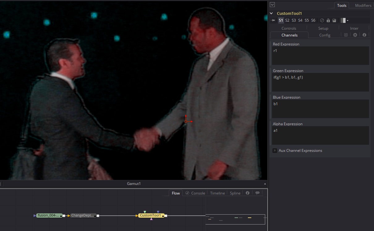
Wow. Look at that ringing! Let this be a lesson, kids: always turn off the in-camera sharpening. There might be something we can do about that later on by substituting the original Luminance channel after the fact:
But first we need the matte, and we're not going to get it from there! The matte is created with this formula:
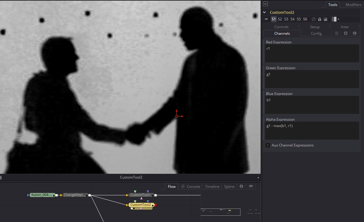
a = g1 – max(b1, r1)
Recall from the previous chapter that the max() function returns the brightest value from the two options. In this case that brightest value is subtracted from the screen color, giving a low-contrast matte, like so:
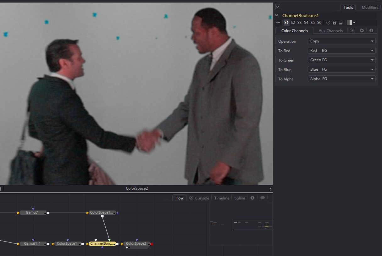
I imagine that noise is going to be quite the problem for this key, but we'll see how it goes. The next step is to threshold this image until the black is true black and the white areas are solid. This is done with a Bitmap tool. The Low and High thresholds are pulled in until a reasonable matte is created. This matte is then multiplied by the desired background image to create a hole in the background, and the result is added to the despilled foreground, resulting in this:
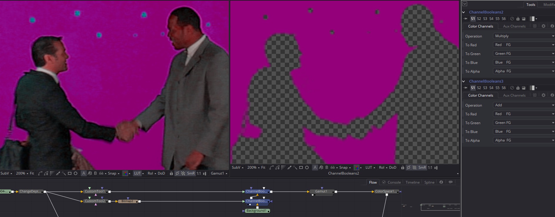
Those are the basics of the method: Two CustomTools, a Bitmap, and two ChannelBooleans. Now that the tool has been set up, let's roll it into a macro and put it to work!
First, we need to determine what our inputs and outputs are. We'll need an input for the greenscreen Foreground and one for the Background. We'll also need an Output for the composite, and since sometimes we might want just the matte, we'll set up an extra output for that.
In terms of controls, we'll need to expose the threshold on the Bitmap tool. In the event that the despill is too strong, we might want a control to blend between that and the original plate. The Blend control on the spill suppressing CustomTool should be sufficient. It's entirely possible to set up dozens of other controls and tools inside a macro like this one. My own implementation has five tabs worth of controls. (It's still in internal testing at MuseVFX; I don't have permission to distribute it at this time. It's awesome, though!)
I'm going to create a little extra complexity before making the macro. First, let's set this up so that it takes a linear input. That way we don't have to have any caveats for the tool that it works best in sRGB or some such nonsense. So, put in a Gamut set to convert from No Change to sRGB. To compensate, we'll go ahead and add the usual Gamut to our footage. Put in another ChangeDepth node right before the Gamut to ensure that we're in floating point, regardless of what the user does. If you want to, you can expose the depth control in the Macro, in case the user decides they really need to pull their key in int for some reason. We'll leave a Gamut at the back end as well for converting back into linear. The user need never know what gamut we're doing our work in.
Move anything that isn't going to be part of the Macro well away from the rest of the nodes. We don't want to accidentally catch a stray Gamut or that magenta Background tool in there. Next, let's rename some of the tools so it's easier to remember what is doing what. I'm going to call the first Gamut lin2srgb and the other one keyOut. The ChangeDepth will be called keyIn. To rename a tool, select it and hit F2. CustomTool1, where the spill suppression is happening, I will call spill. CustomTool2, where the matte is being pulled, I will call pullMatte. The Bitmap has controls that will appear in the control panel, so I'll call that one simply matte. The first ChannelBooleans handles the background, so I'll call it bgIn. The other ChannelBoolean creates the composite, so I'll call it comp.
Now we need to arrange things so that the controls appear in the right order. Remember, the inputs will be arranged by the physical location of the tools, top-down and left-to-right. I'm not sure which takes precedence. Here's how I'm arranging my Flow:
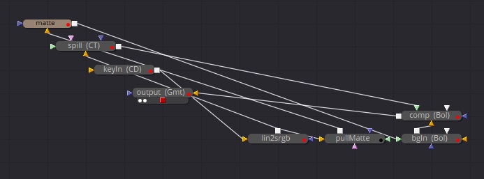
It looks pretty messy like this, which can make it difficult to troubleshoot if you come back later on. As you make more advanced macros, you'll start to construct your control panels by hand in the text editor, and this kind of construction will no longer be necessary. For now, though, it's the simplest and easiest way to get things done.
Select all the nodes, right-click and Macro > Create Macro… In the Macro editor, the tools should be arranged in priority order according to how you laid them out in the Flow View. Unfortunately, it looks like mask tools take a backseat to other kinds of tools, so the matte is below spill. That's alright, though. It just means the spill suppression slider will be at the top instead of the matte threshold sliders. Activate the Blend control in spill (it's way down near the bottom in the Common category) and name it Spill Suppression. Activate High and Low in matte/Controls. Also activate Mask, which is the name of the output on that tool. Activate the Input in keyIn and name it Foreground. Also activate both Depth and Dither on that control. In output, activate Output. We hadn't originally planned on it, but also activate the all of the controls except for TempSourceSpace, TempOutputSpace, RemoveGamma, OutputSpace, and AddGamma in the Controls tab of lin2srgb in order to allow the user to designate the incoming gamut. We'll use the text editor to set up a tab to hide those controls away unless they're needed. Finally, check Background on bgIn.
Give the Macro a name. I'm going to call mine ColorDiffKey and hit the Close button. Save it in the default location, and test it by adding it to the Flow and hooking up the Foreground and Background. Test all of the sliders to be sure that they work. I find that Spill Suppression doesn't, and it's easy to figure out why: The point was to suppress the backing color to black and then simply add it to the background. If the spill suppression is reduced, the backing color brightens back up, and when it's added, it is no longer being knocked out. We have the option of going back into the network to try to fix it, or we could simply delete that slider from the control panel when we touch things up in the text editor. I'm going to opt for the latter, but see if you can't figure out how to fix the problem on your own.
With the keyer selected, add a Brightness Contrast tool to it. You'll find that the keyer connects automatically to the Effect Mask input, and when you look at the BC, you're looking at the matte. If you look at the keyer, though, you see the composite. At the moment, the first output in the list is the one that new tools attach to, but the last output is the one displayed when you view the tool. I am not aware of any solution to this behavior, but it happens to work out okay here since it's best to view a keyer's matte as you're dialing it in, anyway. Another foible of this macro is that the matte is reversed—white is the background and black the foreground. That's another thing that is pretty easy to fix, and I'll leave it to you to figure out how. For now, let's fix up the ins and outs in our text editor.
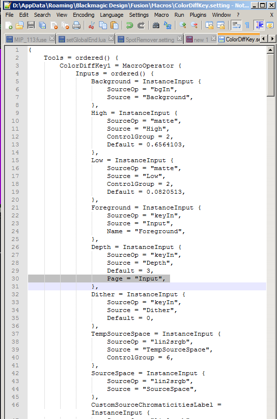 Here's a screenshot of my Notepad++ document (click to enlarge). Highlighted is a line that will add a tab to the control panel. All of the controls that appear after that line will go to a new tab called "Input." After having deleted the Spill Suppression slider, that leaves only the threshold controls in the main tab.
The only thing I've done other than the renaming of inputs you can see here (I left the Gamut control's inputs alone—there were just too many to be bothered with for this little project) is to rename the Outputs and swap their order. Now new tools will get the composite, and putting the tool in the Viewer will show the matte.
All of that having been done, I have to admit that I don't actually care for this method's spill suppression. In my own keyer, I replaced that part with Fusion's Matte Control. It requires you to feed the matte into the Garbage Matte input to knock out the backing color, but it is otherwise the same process. I also should confess that this footage is not ideal to show off the algorithm. If you'd like to put it through its paces with something a little higher quality, try downloading some of the greenscreen footage from Hollywood Camera Work. (Which was, incidentally, shot with the very same model of camera as my horrid footage.)

Share Your Macros!
By their nature, macros are easy to modify and easy to share. Fusion depends on an active and helpful user base that shares tools and techniques. If you develop a macro that you think will be of use to the community at large, please think about sharing it. The We Suck Less forum at SteakUnderwater.com is an excellent place to share out what you've made and learned. And you're bound to get some constructive criticism and guidance to help you take your skills even further. Feel free to build on what you find out there and pay it forward with new tools of your own.
In the next chapter, we'll turn our attention back to more creative topics by examining Fusion's 3D system and how it interfaces with other software such as PFTrack and 3DS Max.
Your article is very helpful to me, but the text description, I looked easy to chaos, if you have time, then you can not write the back of the macro steps and methods recorded video, so that better!
Are you using Google Translate or something similar? I am not certain that I understand. If you're saying that you find it easier to follow a written tutorial than a video, then I agree! That said, several people have requested video tutorials, so I will probably make a few eventually.
Hello Bryan,
Yes. I am not a native English speaker so I translated with Google Translate. If possible, would you please introduce what format do you export files and data from Fusion to import into 3D softwares, such as Blender? I found DNxHR doesn’t work well and it’s not quite compatible. What kind of format do you use between Fusion and Blender? I’ll appreciate it if you can answer this question when you are available! Hope I make sense to you this time.
and data from Fusion to import intonon-linear editing softwares, such as Premiere pro or Edius.
3D software is not good at playing video, so you should use an image sequence instead. The image format depends on what you need to do with it. For viewport backgrounds, jpeg is best for its small file size and fast loading. If you want to use the plate as a light source or texture, then OpenEXR is best.
For non-image data—3d cameras and geometry—the only option is FBX. There are several different versions of FBX, and all of them are slightly broken in different ways, so it takes some experimentation to find which version works best with the 3d software you're using.
Editing software usually works well with video—DNx is a good choice. Fusion isn't the best tool for encoding video, though. We usually render to DPX frames from Fusion then use Thinkbox's Draft (part of the Deadline render manager) to encode that to video. Fusion 9 now has the ability to call FFMPEG rather than using its own encoder, but I haven't yet tried that.