In order to get some early feedback on this chapter of a forthcoming book, I am publishing it early. There are references to other chapters that have been written but are not currently published.
Computer Graphics is half art and half science. Some practitioners lean more one way or the other, but all of us blend both disciplines in our work to some extent. Expressions are one way in which you can bring a little bit of engineering into your compositing workflow. They allow you to automate animation, to connect the properties of one node to another, and to use programming techniques to make your tools more responsive and interactive.
In this article, I will take you through several applications of expressions and start to set up a foundation on which we will build a solid understanding of tool development, scripting, and automation in Fusion.
First, what is an expression? In math terms, an expression is a mathematical "sentence." It is composed of one or more operations that, when evaluated, produce a single numeric value. You can use specific numbers or reference another control that produces a number. For instance, here are two ErodeDilate nodes that have been connected together by an expression:
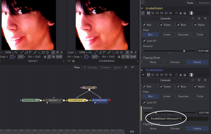
The control ErodeDilate1.XAmount is multiplied by -1 in order to invert it. Now, whenever the Amount control in ErodeDilate1 is moved, the Amount control in ErodeDilate2 moves the same distance in the opposite direction. This trick is useful for removing small blemishes like this mole without changing the contour of the face.
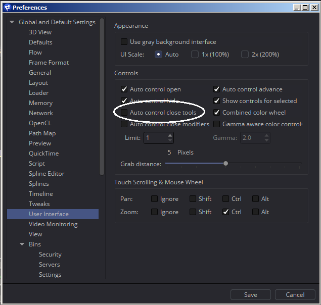
To create a Simple Expression like this one, right-click the control and choose "Expression" from the context menu. Or you can replace the value in the text box with the = sign. If you have made expressions in After Effects, you are probably already familiar with the pick whip. Fusion also has a pick whip: the "+" to the left of the expression field can be dragged to any other control to insert that control's name into the expression. Fusion's default behavior, though, makes it difficult to use this feature because if you select multiple tools, only one control panel will remain open. You can force a control panel to stay open by using the pin icon in the upper left of the panel, or you can disable the auto-close behavior in the Preferences: File > Preferences > Global and Default Settings > User Interface. Uncheck "Auto control close tools."
Expressions for Procedural Animation
Keyframe animation, while flexible, can be quite tedious. Expressions can be used to automate animation tasks and, in so doing, make revisions and precise control much easier. In this lesson, we'll animate a side-scrolling landscape with several layers of parallax and a car to drive through it.
To get started, download this file that contains a Fusion 8 comp and two pieces of public-domain clip art: 007_expressions_files.zip
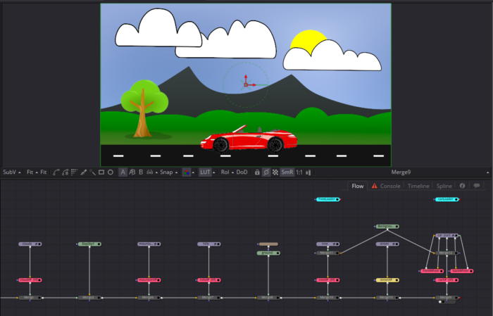
There are a couple of extra bits in this comp that I haven't discussed before. Note the two cyan Loaders in the top row that don't appear to be connected to anything. Just below each one is a Group that contains a node called Wireless Link. The Wireless Link allows you to create a connection between two nodes without a visible wire between them. It wasn't actually necessary to use it here, but I made the Groups before I realized that I wanted to leave the Loaders outside.
The second oddity is that the Loaders don't point to an absolute path. Instead, they use the Comp: Path Map to reference the current location of the comp file itself. As long as the assets are located in the same folder as the comp, they'll remain connected.
The comp itself is fairly simple. I've used some free assets I found online and a few shapes that I drew myself to construct this little scene. Most of the work we do here will be in the pink Transform nodes. The Transforms' Edges control is set to Wrap, which lets us scroll endlessly without running out of pixels. As the image moves off one side of the frame, it reappears on the other. We will set expressions on each Transform's Center control, and for the car's wheels we'll set expressions on the Angle to cause them to rotate.
This scene will be animated procedurally, which means that the motion will be determined by computer instructions (procedures) rather than by keyframes. By the end, we will have complete control over the speed of the car and the distance between each piece of the background without having set a single manual keyframe. The critical element that will allow us to accomplish this feat is the time variable. You can use the word 'time' in an expression to insert the current frame number into the formula. This permits you to create animation that changes as the comp plays without having to set any actual keys.
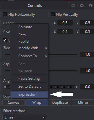 Let's start in the streetXF node. Right-click on the Center control in the Tools panel (not the widget in the Viewer) and choose "Expression."
A new field appears under the Center control prefilled with the Point() function. Point() returns two-dimensional position information to the control, allowing the expression to affect the X- and Y-coordinates in different ways.
Since the expression is now controlling the Center, you can no longer drag the widget in the Viewer, although both the Pivot and Angle widgets still function as usual.
To create the illusion that the car is driving on the road, we want to move the Center to the right—increasing in value—as time goes by. To start, replace the first '0.5' with 'time':
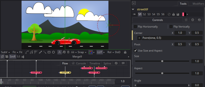
As you can see, my playhead is at frame 1, and the X value of Center is 1.0, placing the widgets on the right edge of the frame. Although the image now ends in the center of the screen, the Wrap feature simply brings the street back in from the left.
If you play the animation, though, it will look like nothing is happening because each frame moves the image by an entire screen width. We need to slow the translation down so that we can see what's happening. Let's suppose we want the street to go by at a rate of one screen width per second. The comp's framerate is 24 fps, so if we divide time by 24, we'll slow it down enough that we can see it. The expression should now be Point(time/24, 0.5).
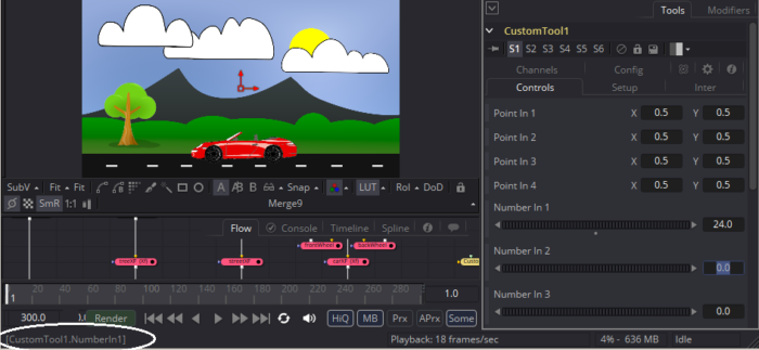
If this were a job for a client, we would be wise to expect changes to the car's speed, so it would be a good idea to have an easily-accessed control for the speed. Add a CustomTool to the flow. It doesn't need to be connected to anything; we're just going to use its numerous sliders to build a control panel.
The CustomTool is one of my favorite Fusion nodes. We'll explore its power more fully below, but for now we're only interested in the sliders it provides. The Controls tab has four Point controls, eight sliders, and four LUTs, none of which do anything on their own. Set the control Number In 1 to 24, then go back to the streetXF node and replace 'time/24' with 'time/CustomTool1.NumberIn1'.
If ever you need to find the name of a particular control, it shows up in the lower-left corner status bar when you mouse over the control's label:
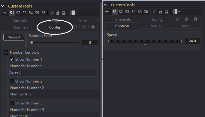
Now the speed can be adjusted by moving the CustomTool's slider. Remember that since the speed is in the denominator of our expression that higher values cause the car to go slower, which isn't ideal. When you're done with this lesson, give some thought about how you might make the Speed control more intuitive. Be careful not to set the slider to 0, or Fusion may crash (Fusion 8 seems to have fixed that problem, but Fusion 7.7 chokes on a divide by zero). If you want to change the label of the control so you remember what it's doing, go to the Config tab of the CustomTool. You can also hide all of the controls you aren't using in order to keep your panel clean and easy to read.
The street is our baseline element. The motion of all the other set pieces will be relative to that one. The next-closest piece of scenery is the tree. Set an expression on treeXF's Center just like you did on the street's. This time, instead of setting its speed explicitly, we're going to connect it to the street's Center, then give it a multiplier to slow it down even further.
If you use the pick whip to choose the control you want to link you will get an error in the Console:
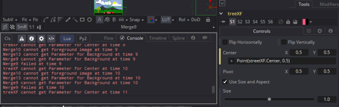
This happens because Fusion is expecting only a single number for each part of the Point() expression, but a Center control is actually two numbers. You need to tell it which of the two numbers it's supposed to read. The correct expression is:
Point(streetXF.Center.X, 0.5)
Adding the .X tells the Point() function that you want the X coordinate value from the Center control. Once that's done, the tree and the street both move at the same rate. Since the tree is further away, though, we want it to move slower. That's as simple as providing a multiplier:
Point(streetXF.Center.X * 0.5, 0.5)
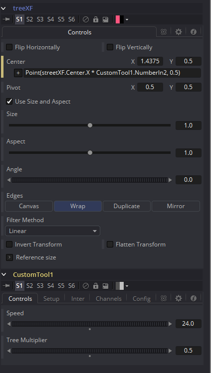 Now the tree moves half as fast as the street. For easier control, we can remove that multiplier out to the CustomTool as well, as shown to the left.
Put a similar expression on each of the remaining scenery elements: the hills, mountains, and clouds. It's up to you whether you want to make each layer independent of the others by connecting them all directly to the street or to cascade them. There are advantages and disadvantages to each method. I'll let you figure out what they are through experimentation.
The last task we need to perform in this lesson is to rotate the tires. We want to again link the tire rotation to the street animation. This time, though, we need a very specific formula based on the tires' diameter and the street's speed.
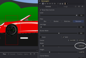 In one complete rotation of the tire, it will travel a distance equal to its own circumference. Therefore, we need to relate the distance traveled by the car (that is, the speed of the street) to the tire's circumference in order to find out how long it takes to perform a complete rotation. The formula for the circumference of a circle is π * diameter. The simplest way to find the diameter of the wheel is to bracket it with a Rectangle tool and simply note the width. Although the wheel is circular and therefore radially symmetrical, the width and height measures are different because Fusion tools express their dimensions as a percentage of the screen, not as real units.
You could calculate the circumference yourself and make a note of it, but I'm going to just let Fusion do it. I'll expose another slider in my CustomTool, call it Tire Circumference, and give it the expression pi * Rectangle3.Width . That does mean 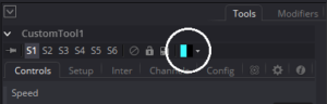 I'll have to keep the Rectangle in the comp, though. I am gathering a few tools that are in use but not connected to anything. To remind myself not to delete them, I think I'll give them that same cyan color as the Loaders. You can change a node's color using the icon I've circled. The pop-down menu lets you quickly select a color scheme that you have used elsewhere in the comp.
Now we come to a little bit of a hairy math problem.
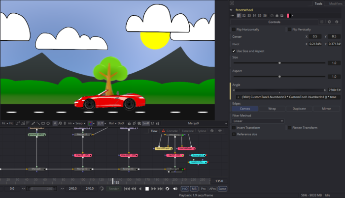
We know how many frames it takes for the car to travel one screen width—that's given by the Speed control. We also know the percentage of the screen width the tire covers in one rotation—that's the Tire Circumference. So the time required to travel that distance (and thus one rotation of the tire) is simply Speed multiplied by the Tire Circumference. The Angle control uses degrees, so we now need to divide 360 degrees by the time required for a full rotation. That yields how far the tire should turn on each frame. Finally, multiply by the current time to perform the actual rotation. The full expression is:
360 / (Speed * Circumference) * time
Fusion uses the same order of operations you learned in Algebra: Parenthesis evaluate first, followed by exponents in left-to-right order, then multiplication and division, then addition and subtraction. Here, the parenthesis ensure that the denominator of our fraction is evaluated first.
Naturally, you'll need to substitute in whatever actual control names you've used. This expression will go in the Angle control of both the frontWheel and backWheel. And that's it! You've animated the scene without setting a single keyframe. Turn on the motion blur and let it play to see the results of your labors.
Per-Pixel Expressions with the Custom Tool
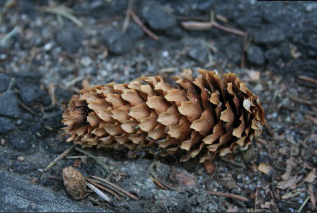 As promised, let's look harder at the Custom Tool. Nuke users may have already encountered something similar in Nuke's Expression node. Create a new comp and add a picture of your choice. It doesn't matter what it is. I'll be using this pine cone.
Add a Custom Tool to the flow and switch over to the Channels tab. On this tab, each available channel is given a short code that can be used in expressions in the tool. r1, g1, b1, and a1 are variables that receive the red, green, blue and alpha channels of Image 1 (the background input—mouse over the gold input on the tool to see that the name given in the status bar is CustomTool1.Image1). The Custom Tool can also take two more images: Image2 and Image3. As you might have guessed, if you want to get the red pixels from Image2, you would use r2.
With these default settings, the CustomTool simply passes the values of each pixel from the input to the output without a change. If we put formulae in these fields, though, we can perform calculations on the pixels before they are sent out. For instance, in the Red Expression field, type 'r1 + n1' (without the quote marks). Nothing appears to happen because 'n1' is a short-cut variable that gets its value from the Number In 1 slider on the Controls tab. Switch back over there and drag Number In 1 back and forth. The value of the slider is being added to the red channel, so you can tint the image red by giving it a positive number or cyan (the complement of red) by giving it a negative. If you also add n1 to the green and blue channels, you will have a Brightness control, identical to the one in the Brightness/Contrast tool.
We can do much more interesting things than just building color correctors, though! Go back to the Channels tab and replace the Red Expression with 'x'. The red channel is replaced with a horizontal ramp from 0 to 1. The x-coordinate of each pixel has been assigned to the red channel. By using the x- and y-coordinates of a pixel, you can create patterns.
Try x % n1 and go back to play with the Number In slider again. The % operator is one you may not have run into before if you're not familiar with programming. It's called the modulo, and it will return the remainder of a division. A % B gives the remainder of A/B. So x % n1 creates a gradient that resets every time x is equal to a multiple of n1. Add y % n1, and you'll get a repeating gradient box like this:
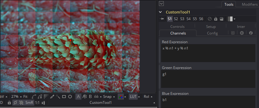
Putting the same expression in each channel box will overwrite the picture entirely, giving you only the gradient boxes. We can also use the Custom Tool's Point controls to move the pattern around. Try this:
(x – p1x) % n1 + (y – p1y) % n1
p1x and p1y are variables that receive the values of the Point In 1 control. By subtracting them from the x- and y- coordinates in the expression, you can shift the pattern by using the Point In 1 translate widget in the Viewport. And once again, I'm using the parenthesis to force Fusion to evaluate the expression in the order that I choose. Modulo evaluates at the same level as Multiplication and Division, so if I don't use the parenthesis, I'll get the remainder of p1x / n1 subtracted from the pixel's x-value, which is not what I want.
You can also use math functions in expressions. A function is a pre-built piece of code that usually looks like this: function(). It takes some input, which goes inside the parenthesis, does some kind of processing on it, and spits out a result. Fusion uses the Lua scripting language, which has a standard library of math functions. Let's play with some trigonometry!
The trigonometry functions sin(), cos(), and tan() produce repeating wave patterns. A simple sin(x) creates a smoothly oscillating wave cycling from 0 to 1 to 0 to -1 and back to 0. The trig functions are all related to circles, and Fusion measures circles in degrees, so the cycle will repeat every 360 units.
To start, let's just plug that sin(x) function directly into the Red Expression. At first, it produces a very dim gradient because our greatest value at the right edge of the screen is only 1, and sin(1) produces a very small number. If we multiply x by 360, though, we'll get the full wave:
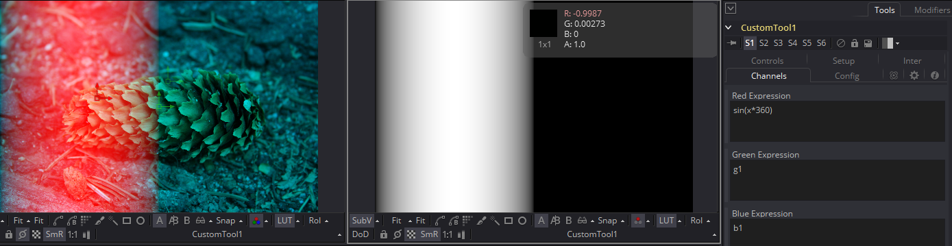
I have turned on the color inspector and placed my mouse over the image at about x = 0.75 so you can see that the red values are around -1, as expected from this kind of wave. Negative pixel values are not usually useful, so let's do a little arithmetic to normalize this wave from 0 – 1. Normalization remaps values from one range to another without changing the internal relationships of the numbers. That is, we're going to change this wave with its range of -1 to 1 into a wave with a range of 0 to 1.
First, we need to increase the brightness of the wave so that the smallest value is 0. Simply adding 1 to every pixel will do it: sin(x*360) + 1. Now we have a wave with a range of 0 to 2. Knocking it back down to our desired range is as simple as dividing every pixel by the maximum possible value: (sin(x*360) + 1) / 2
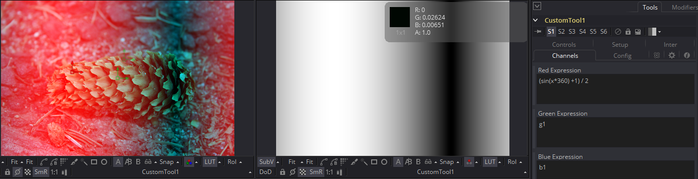
No more negative pixels, and no super-whites, either. The same math can be used to convert 8-bit integer RGB values that run from 0 – 255 to normalized values from 0 – 1. Fusion normally does this automatically, but there may be occasions when you will find it useful to be able to normalize an arbitrary range.
Now suppose we multiply by n1: (sin(x * 360 * n1) + 1) / 2. We get a pattern of alternating white and black lines, with Number In 1 controlling how many lines there are. You can do the same thing in the y direction and combine the two for a grid of soft diamonds: (sin(x * 360 * n1) + 1) / 2 + (sin(y * 360 * n2) + 1) / 2
That creates more super-white pixels. Since the maximum value of each wave is 1 and we're adding them, our new maximum value is 2. We could simply divide the entire expression by 2 again to knock it back into range, or we could use another function to take the maximum value between the two. The max() function compares two values and returns whichever one is higher. There is a similar min() function that returns the lowest of the two values. It's possible to call functions from within functions, so if we wanted to use max() here, it looks like this:
max((sin(x * 360 * n1) + 1) / 2, (sin(y * 360 * n2) + 1) / 2)
Since max() takes two inputs instead of just one, we use a comma to separate them: max(input1, input2). Here is a comparison of the results of each of these two expressions. Divide by 2 on the left and max() on the right:
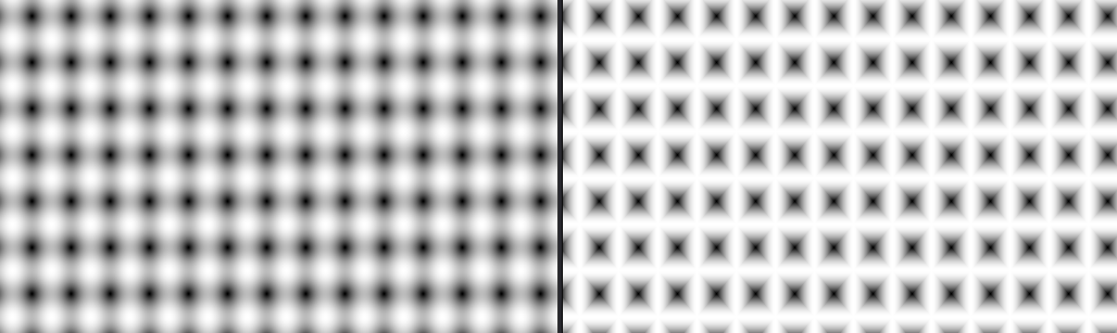
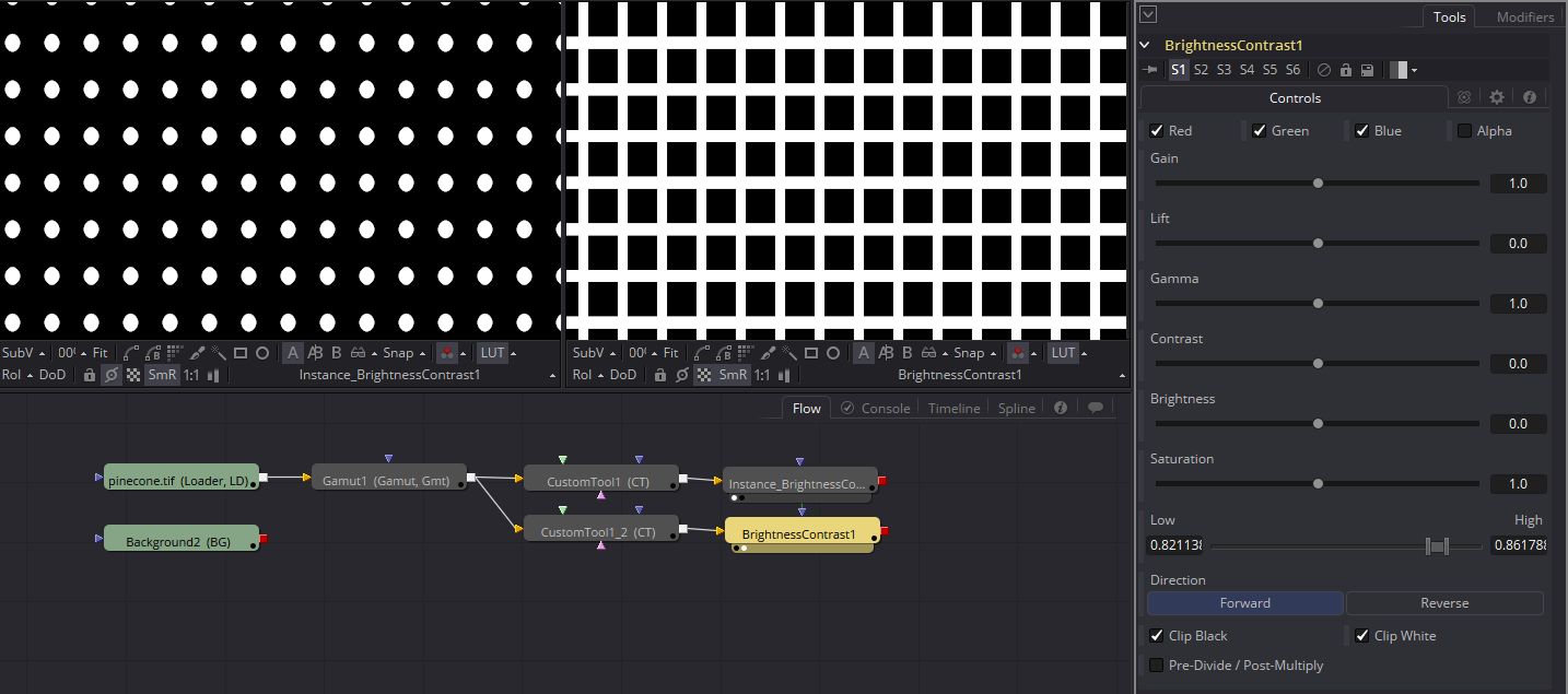
If you use a Brightness/Contrast to threshold the result, you can harden the lines and dots and control their size by simply sliding the range back and forth:
You may have noticed that I started using n2 to control the y frequency. That lets me control the aspect ratio of the boxes. If you want to make sure they're always square, you can even link n2 to n1 by determining the aspect ratio of your screen. In this case, I've assumed I was using a 16:9 HD frame, but in fact my photograph is 3:2, so my boxes are not quite square. Suppose I wanted to force squareness without regard to the actual dimensions of my input image? Every image knows its own Width and Height, and you can use that information in your expressions. In this case, CustomTool1.Image1.Width has a value of 1728, the width of my pinecone image, and CustomTool1.Image1.Height has a value of 1152.
I want to control Number In 2 using Number In 1's slider, and I want the two ratios NumberIn1:NumberIn2 and Width:Height to be equal. I have two ratios with three known values; I recall from my Algebra lessons that to find the fourth I can cross-multiply. NumberIn1 * Height / Width = Number In 2. So the expression for Number In 2 is:
NumberIn1 * Image1.Height / Image1.Width
The shortcut codes n1 and n2 don't work outside the Channels tab, so you have to give the full control name to the expressions in the Controls tab. Now you have grids that will always be square, regardless of the aspect ratio of the input image!
At the very top of this article, I mentioned that Fusion's CustomTool is similar to Nuke's Expression node. With that in mind, the Expressions 101 by Matt Estela on Nukepedia has some more exercises you could try. The concentric rings portion will be particularly instructive because Fusion doesn't quite work the same way as Nuke. Troubleshooting that effect can teach you a lot about how to tinker with your expressions until they do what you expect. You should also look through the Custom Tool entry in the Fusion Tool Reference. The relevant entry begins on page 453.
Something to Look Forward To
The next step forward is to learn about macros. Back in the Rotoscoping and Keying chapter, I mentioned that Fusion had some room for improvement regarding keying tools. In the next chapter, we'll try to fill that void by using what we've just learned about expressions to develop a color difference keyer based on a description from Ron Brinkmann's The Art and Science of Digital Compositing.
Thanks Bryan! It's really useful
I'm glad you like it! Any recommendations for improvements are welcome. I should put up the Macros chapter in a couple of weeks if all goes well.
Hey Bryan!
Because there is no official manual on expressions I tried to make it streamlined in my own workflow by using the regular expressions in fusion that I used to use in After Effects. I do encountered some roadblocks like how to use the "value" keyword in fusion which basically preservers the original value + executes your expressions. and how to use conditionals and looping.
Today blackmagic tweeted that they have released Fusion 8.2.1 which has "more expressions".
I don't know what do they mean by that.
The Value variable doesn't seem to have an equivalent in Fusion, at least as far as I have found. I'm actually struggling with that problem right now in a macro I'm building. You also can't have an expression that references itself, so it's not possible to use the GetValue() function to query, for instance, its value at a previous frame. I have a notion about trying to do it indirectly by setting up a second control and using GetValue on that, but I'm not sure if it will work.
As for conditionals and loops, they're possible, but you need to know a trick. If you start your expression with a colon, you can make a multiple-statement expression. Each statement needs to end in a semicolon, and there are no carriage returns allowed, so it all has to go on a single line. For instance:
:if(controlValue < 1) do n = anotherControl+time; else n = time; end; return nThere are some additional samples in this thread at the We Suck Less forums:
http://www.steakunderwater.com/wesuckless/viewtopic.php?f=6&t=796
You can also learn a bit more about expressions in the VFXPedia:
http://www.steakunderwater.com/VFXPedia/96.0.243.189/index4aa9.html?title=Simple_Expressions
And a little from the Fusion 8 Scripting Guide:
http://documents.blackmagicdesign.com/Fusion/20160317-c992b2/Fusion_8_Scripting_Guide.pdf
Though it just barely mentions Simple Expressions, there are a few tidbits you can glean from other parts of the document, especially now that you know about that : trick.
Thanks Bryan!
Just stumbled on this. Big thank you to Bryan for sharing this! It's a huge help (and the following section on macros), especially considering how sparse BMD's official documentation can be.
Glad it's useful!