
The lines between 3D and 2D visual effects tasks are blurring more and more. Nuke and Fusion both have useful 3D toolsets built in, and After Effects users can use the powerful Element 3D plug-in. Most 3D programs have 2D tools built in, and some, like Blender and Houdini, are even capable compositors themselves. For now, 3D and 2D are still distinct roles in most facilities, but each new software release brings the two closer together. A compositor should therefore understand 3D systems in at least broad strokes.
A comprehensive education in 3D software is beyond the scope of this book, so the information presented here is, by necessity, somewhat shallow. First, an overview of a typical 3D workflow: The first thing a 3D project usually needs is geometry. This geometry can be referred to by several terms; mesh, geo, and model are the most common. In typical usage, these three terms are synonymous.
The geometry is merely the shape of a 3D object. There is nothing inherent to the mesh that describes its surface qualities. That information is supplied by shading the object. Materials (also called shaders) determine how the surface interacts with light that hits it, and textures control the properties of the materials at every given location on the mesh. The words texture and map usually mean the same thing: a 2D image file that is applied to the mesh to modify its surface properties.
If the object requires any special controls to move it around, then it must be rigged. A full character rig is technically possible in Fusion, but it would not be easy or convenient, so usually only the simplest of animation rigs are used in the compositor. Flapping wings or simple mechanisms are the most you are likely to see.
A virtual camera must be created at some point in the process. In a visual effects shot, this may come from a matchmove or tracking department that has recreated the camera used on a live action set.
Animation is the next step. It depends on having a finished model and usually a rig. Keyframes are set for the geometry's position and pose at different points in time, allowing it to move.
Lighting is the process of creating virtual light fixtures to illuminate the model. Lighting and shading are companion processes—changes to one will often cause changes in the other—and set-up of the renderer is often also the job of a lighter.
All of these processes can be performed in Fusion to one degree or another, but dedicated 3D software will do all of them better. That said, doing your shading and lighting in the compositor can give you significant speed advantages over having to render elements. In the lesson below, we'll see how Fusion can be used to import 3D geometry to be quickly lit, rendered, and integrated into a photograph.
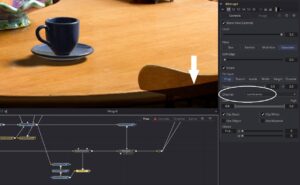
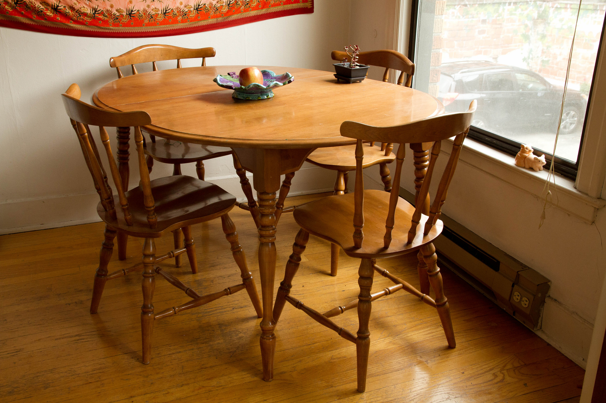 For this lesson, you will need the coffee cup geometry and this image of a table, courtesy of Flikr user Helen Cook (Creative Commons Attribution-Sharealike 2.0). Click the image for a full-size version.
Our objective is to create a photorealistic render of the cup and integrate it into the scene such that it looks like it was on the table when the photograph was taken.
Start by importing the image and converting it from sRGB to Linear color space. Take note of the unusual resolution: 2048 x 1365. In order to integrate our CG cup with this image, we'll need to either reformat this image to a more standard size or set our renderers to the larger resolution. Generally speaking, you want to give the image back to your client in the same condition as you received it, meaning that the proper approach should usually be to render the CG at the plate's resolution.
Camera Matching
The success of a composite like this one is very much dependent on matching the camera—if you have the wrong angle and/or lens, it is much more difficult to make a convincing image. Although it's tempting to go ahead and bring the cup itself into the Flow and try to line it up by eye, it's a better idea to roughly model something that's already in the plate and use that as a reference for where the cup should go. In any empty spot in your Flow, add a Shape3D tool (3sh) and View it. Shape3D is a flexible multi-purpose primitive object. Its default setting is a plane with its normals (a vector perpendicular to an object's surface) pointed toward positive Z.
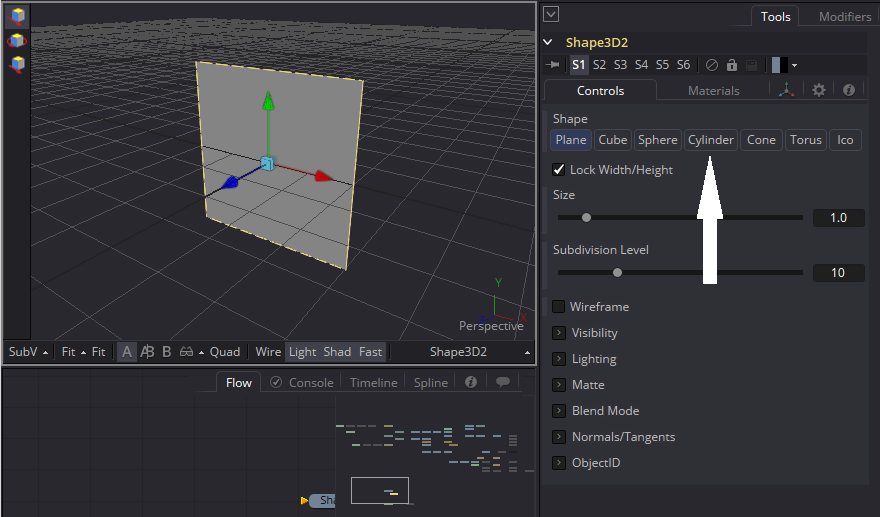 Click the Cylinder button in the Shape3D's Control panel to change its shape. The shape in your 3D Viewer will change into a cylinder with its top and bottom open. With a few adjustments to its shape, this will become the surface of the table, which we can use to accurately line up a camera.
It's likely that the cylinder is a little bit too large to be comfortable seen in your Viewer. Let's go through some new navigation controls that are specific to the 3D View. As with any other panel, the middle-mouse button (MMB) can be used to pan around the Viewport. If you don't have a middle mouse button, Ctrl+Shift and left-mouse (LMB) will do the same. Holding LMB+MMB and dragging will zoom in and out. The +/- keys will do the same. To orbit the camera around the center of the screen, hold Alt+MMB and drag. Or Ctrl+Alt+Shift+LMB. If you've moved your Viewer around too much and can't seem to get back to your scene, the F key will Frame the visible scene. Or if you have a mesh selected, F will Frame that object.
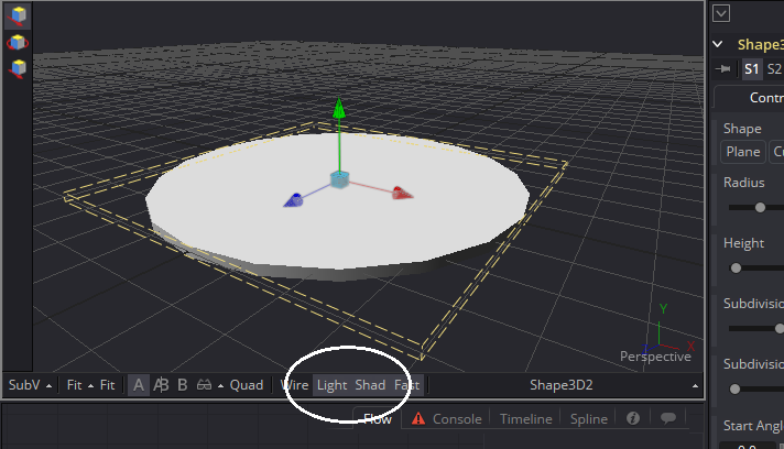 Once you have familiarized yourself with the nav controls, get a nice, comfortable view of your cylinder. We'll need it to match the shape of the table a little better, and the top surface is going to be important, so let's start by reducing its Height and activate the Top Cap switch. It's probably now hard to see the shape since Fusion's workspace has shading turned off. At the bottom of the Viewer, click the Light and Shad buttons to turn on lighting and shadows. Fusion's default lights will be activated. Note, however, that there are no lights actually in the scene. If you were to add a Renderer and activate Lighting there, you would see a black screen. The default lights are only used in the Viewport. We don't know the actual dimensions of the table, but I guess it to be a little more than a meter wide. Fusion's grid is unit-less: the grid lines can represent any distance you please. I'll tell you in advance, though, that the coffee cup is modeled in centimeters. I'm going to assume that the dark grey lines in my grid are 1 meter apart, making the cylinder 1 meter in diameter. It doesn't actually matter so much for this scene, but in more complex situations having accurately-sized geometry can greatly simplify the process of laying out a scene.
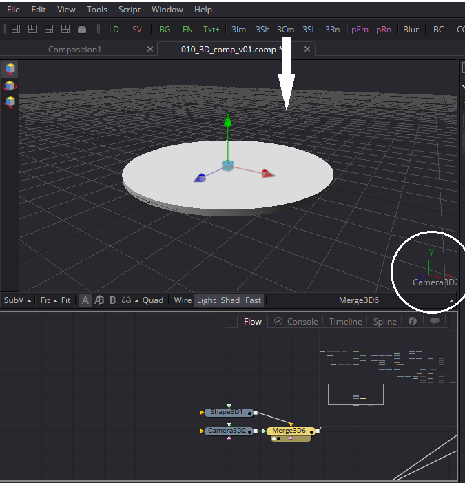 Once you have something that looks like it might be similar in proportions to the table in the photo, create a Camera3D (3Cm). This is one of the rare cases in which how you create a tool makes a difference. Assuming you have a viewpoint similar to the one shown above, you can create a camera that has that exact same viewpoint by dragging the 3Cm button in the toolbar into your Viewer. Note that the View Angle widget in the lower-right of the Viewer changes from Perspective to Camera3D1. This indicates that you are now looking at your scene through that camera, and any navigation you do will be applied to that camera. Since you now have a pivot point (the camera's location), the Orbit control of alt+MMB rotates the camera instead of orbiting around the center. To restore the previous functionality, right-click the View Angle widget and choose Perspective. Now if you move your view around, you should be able to see the camera.
Creating the camera in this fashion automatically makes a Merge3D node and connects both the Shape and the Camera to it, placing them both in the same Flow. Unlike a regular Merge node, there is no concept of "foreground" and "background." In addition, every time you connect a new node to a Merge3D, another empty connection arrow appears, meaning that you can connect as many inputs as you want to it. In addition, the Merge, like most 3D tools in Fusion, has its own Transform tab, allowing you to move, rotate, or scale an entire 3D scene at once. Every input in the Merge3D will be affected by these transforms.
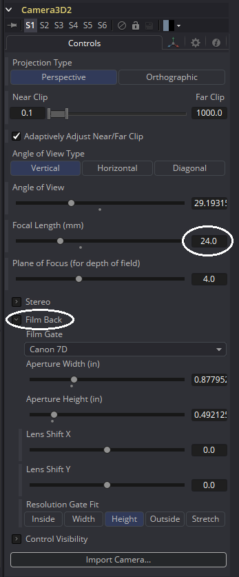 Let's look at the controls on that Camera3D node. There are a couple of things we'll need to adjust before we move on. Whenever you are trying to match a virtual camera to a real one, getting similar angle-of-view properties is crucial. By looking at the photo, we could guess that the photographer used a medium-length lens—the perspective lines are neither parallel nor exaggerated. We don't have to guess, though. The metadata for the photo is available on the Flikr website where we downloaded the photo: A Canon EOS 7D with a 24mm lens.
To set our virtual camera to match, enter the Focal Length of 24mm in the appropriate field. Then twirl down the Film Back controls and choose the Canon 7D in the Film Gate drop-down. Most common professional-quality video cameras have presets in this list, but if you're dealing with a model that doesn't have a preset, you can set the Aperture Width and Height properties by hand. These specifications can almost always be found somewhere on the Internet. Just be sure you take note of the unit of measure. Fusion expects inches, but some manufacturers specify their aperture in centimeters or millimeters.
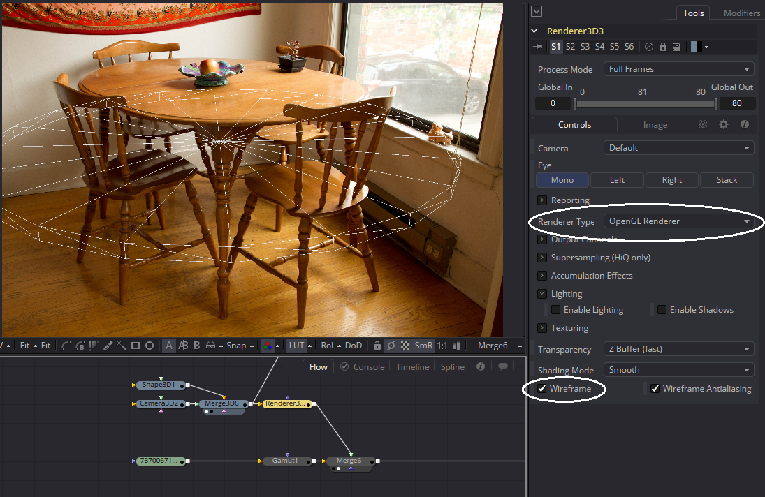
We now have a table that is approximately the right size and a camera that has exactly the correct angle of view. Now we can start trying to line them up. Create a Renderer3D and connect the output of the Merge3D to its input. In the Image tab, set the Width and Height to match the plate: 2048×1385. While you're there, set the Depth to float16. If you view the Renderer, you should see a featureless white disc, much like you saw before you turned on Light and Shadows in the Viewer. To make the line-up process easier, we'll want to see the wireframe instead of a solid object. Unfortunately, Fusion's default Software Renderer cannot do that, even if Wireframe mode is turned on in the Shape3D. To get access to more options, change the Renderer Type to OpenGL Renderer. Now you can activate Wireframe and see the white edges over a transparent background. Merge that over the Plate to see this:
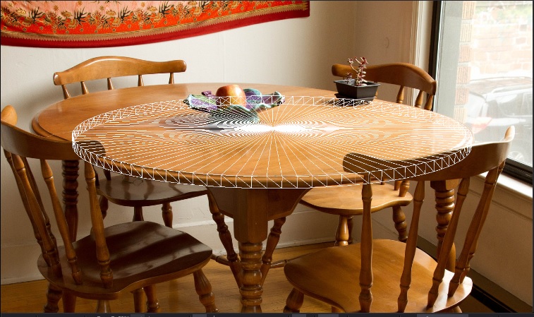
Now comes the tedious job of moving the camera until the surface of the table and the top of the cylinder are aligned. I got pretty close by manipulating the camera, but the angle of the surface was just a little off, so I added a Transform3D between the Camera and the Merge. The Transform3D defaults to a pivot at 0,0,0, so X-Rotations applied there may be a little easier to use. Lining up a camera in this fashion can be frustrating and time consuming. Dedicated 3D tracking software can do it much more easily, sometimes even to the point of automagically creating proxy geometry of the room. (A proxy is a stand-in element of lower quality or accuracy. Proxies can be used to speed up working due to a smaller memory footprint or to let people "downstream" in the pipeline get to work even if the final assets are not yet available.)
The cylinder does not match the entire table, which has a rectangular leaf inserted in the middle, but the only part we need to concern ourselves with is the nearer portion of the surface, so just matching the round front edge suffices.
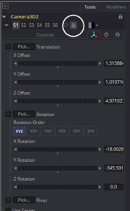
Given how laborious matching a camera can be, it's not a bad idea at this point to lock the Camera. The Lock icon at the top of the panel prevents any changes to the node.
Adding the Geometry
Finally, we're ready to import the coffee cup geometry! And finally, we'll use the File > Import dialogue. Recall from our very first lesson that importing footage using File > Import creates a new comp file. Importing a 3D scene, on the other hand, acts just like you would expect it to—adding new nodes to an existing scene. The intuitive interface design ends there, however. You will notice that although we want to import an OBJ file, which is a very common and basic exchange format, there is no OBJ importer in the list. Instead, we will use the Import FBX Scene command, which unexpectedly opens a variety of different file formats aside from FBX.
The FBX Importer dialogue appears. For the most part, you can leave the settings as they are. I mentioned earlier that the cup was modeled in centimeters, but we're treating our Fusion units as meters. If you want to, you can enter 0.01 in the Scale File Units By box in order to pre-scale the cup to something resembling the correct size. I'm going to just click "OK" without changing anything, though, and do that scaling in my Flow instead.
Five new nodes will be created somewhere in your Flow. They may or may not be on the screen or close to your existing nodes. Sometimes you have to pan around a bit to find them. If you have the Flow Navigator open (V when the Flow view is focused toggles the Navigator on and off), you will probably see the new cluster somewhere. Find them and drag them to a convenient spot near your existing 3D nodes. The new nodes consist of two FBX nodes—one contains the cup and the other the saucer—two generic Blinn materials, and a Merge3D that unites the cup and saucer. If you view the Merge3D, you will see that the new geometry is huge. That is easily fixed in the Transform tab of the Merge3D by changing Scale to 0.01.
You could use the Merge3D to place the cup exactly where you want it, but I prefer to use a separate Transform3D for that purpose. It's up to you which way you go. Looking at the composite, it seems to me that the cup is still larger than I would like. Use the Scale control in the Transform3D to reduce it even further by 0.5. It looks like the right scale now. Use the Transform3D's Translate Y control to put the bottom of the saucer on the surface of the table. It's easiest to do when you're looking through one of the orthographic views. Right-click the View Angle widget and choose Front, Left, or Right. Then use Translate X and Z to place the cup in a good spot on the table. You can adjust the exact location and rotation later on, so don't agonize over it at this point.
Lighting
Before we move on, a caveat: There are a few compromises we'll have to make due to Fusion's limitations, so don't take this as a general primer on CG lighting. For instance, usually you would use a directional light for the sun, but in Fusion only the spotlight can cast shadows, so we're forced to use it for our keylight. In addition, there is a bug in the OpenGL renderer that permits only one spotlight in the scene. Additional spotlights cause the renderer to fail. Fusion doesn't have any kind of secondary bounce lighting, so reflected light needs to be simulated with additional light nodes. The list goes on. Moving on…
In the Renderer3D, turn off wireframe mode and tick both the Enable Lighting and Enable Shadows switches. The table and cup will both turn black because there are no lights in the scene yet. That's our next order of business. The primary light source in this scene is the large window, so let's add a spotlight to the scene and move it into a position approximately where it will need to go. Put the 3D scene into one Viewer and the composite in the other so you can easily see the effects of your light. We'll use the shadow cast by the cup onto the table as a way to judge when the light is in the right place. It should be similar in direction and length to the other objects on the table. The little black planter is probably the most reliable since the shape is easy to understand. The CG table surface is probably in the way, though, so add an Ellipse mask on the Merge that combines the CG with the plate. Size it so that only the cup and its shadow are visible.
Move the light around until the shadow seems correct. Don't worry about the quality yet—we just want to get the light in approximately the right place.
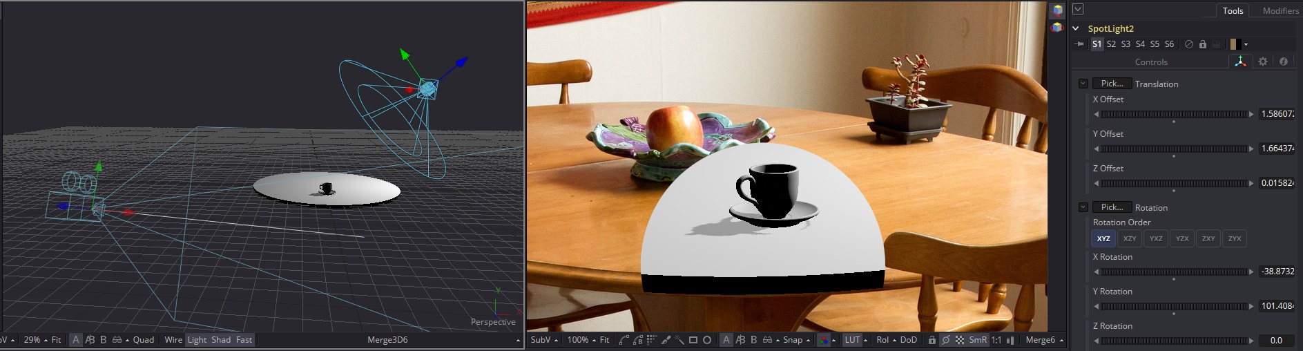
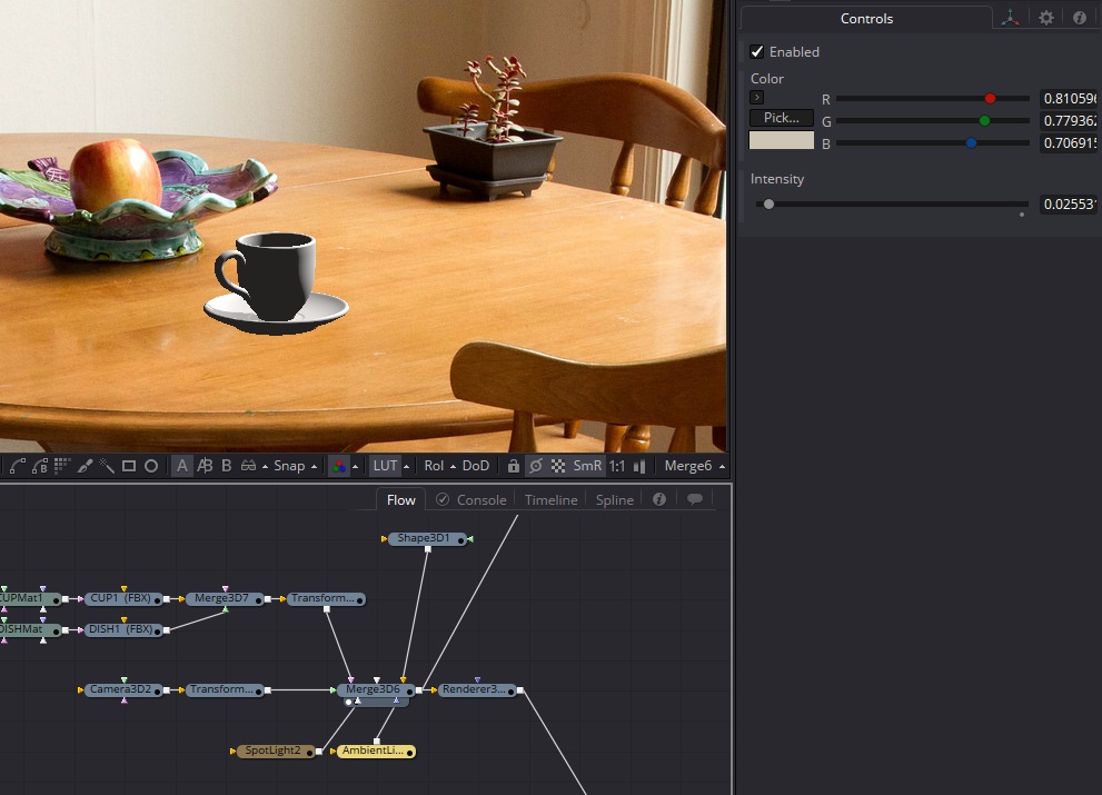
This primary light in the scene is known as the key light, and it's usually the most important one to get right. We have it casting its shadow in the right direction, so now let's get adust its color and intensity. The approach to color matching we used in Chapter Two will work here as well: Find a well-lit but not overexposed neutral color, and use that as a guideline. Setting this color is more straightforward, though, because we can just use the Pick… button to directly select the color out of the Viewport. We don't seem to have anything in the scene that we can be sure is actually white. The walls are the closest, and they look to be some variety of eggshell. That's the best we're going to get, though, so let's go for it. Drag the Pick… button over a well-lit spot on the wall. The light will immediately dim and pick up a warm hue. Knowing that the wall is not quite white, we can counteract its color by slightly boosting the blue. Not too much, just enough to take some of the yellow out. My RGB values are 0.862, 0.835, 0.810. The light is pretty bright, so let's increase the Intensity until we start to get the same kind of blown-out highlights we can see elsewhere in the image. At this point, the table's surface is probably a distraction, so go to the Shape3D node, twirl down the Visibility section, and untick "Visible." Don't worry, we'll get that shadow back in a little while, but for now we don't need to see it. Go back to the Spotlight and adjust the Intensity until the brightest parts of the cup and saucer are starting to clip.
 The lighting is very harsh, with absolutely no color in the shadowed areas. Now we need some ambient light to represent the general illumination coming from all around. Make an ambient light node and connect it to the Merge3D. This one is way too bright, so bring the intensity down until the unlit side of the cup is about as bright as the unlit side of that planter. Sample the color of the wall again with this light to warm it up. We'll come back to lighting in a bit, but at this point we should start thinking about shading.
Shading
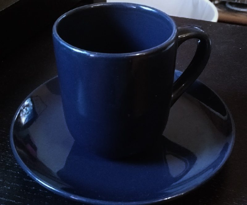 The generic materials that came in with the object aren't very realistic. To simplify things, I'm going to use just one material for both pieces—they're part of a set, so they can get a single shader. Delete one of the material nodes and plug the other into the vacated input. This shader is a Blinn material that emulates clay. While it would make a great moon rock, we're after something more like porcelain. I have a dark blue mug on my desk that I will use as a model for how I want my cup to look.
The first, most obvious quality is the Diffuse Color, which should be a dark, saturated blue. If you single-click the Pick… button, you'll get a new kind of color picker. Below the grid of Basic Colors is a button that says "Pick Screen Color." Clicking that button turns the cursor into a crosshair that can be used to sample a color from anywhere on your screen, including other windows or, in my case, even a second monitor. I sampled a color from that photo of my mug to get RGB values of 0.066, 0.131, 0.313. That's a pretty good place to start, although I suspect the saturation of that color is a little low.
The next quality to address is the specularity. My mug is pretty shiny, with tight, bright highlights, but my material is still dull. Specularity is just a reflection of the lights hitting a surface, so the Specular Color should be the same as the key light. You can sample that color directly from the Spotlight's color swatch, or you can get it from the wall the same way we did before. The highlights are still too broad and spread out, making the mug look like it has a satin finish. In a Blinn, the size of the highlights is controlled by the Specular Exponent control. Turning that up to 95 or so makes the mug look shinier. The highlights are now a little dim, though, so let's give them some more kick by turning Specular Intensity up to 3.
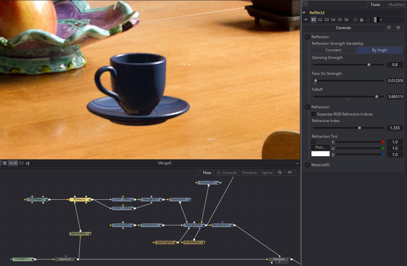
Reflections
Although the specularity makes the mug look shiny, it's still missing something important. As I mentioned, specularity is reflection of lights. But if something reflects a light, it should also reflect its surroundings to some degree. We can add 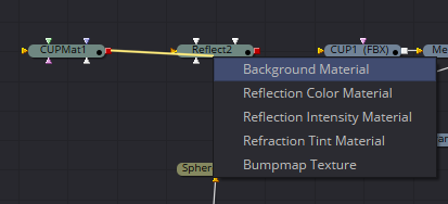 an image-based reflection to the mug with a Reflect node. Reflect adds an additional "layer," so to speak, to the material. It needs to go between the Blinn material we've been working on and the geometry, but it has several inputs, so it's important to feed the Blinn into the correct one. For nodes with multiple inputs, the easiest way I find to be sure I plug into the right one is to hold down Alt when connecting to it. A pop-up dialog will appear asking which input you wish to connect to. Choose "Background Material." Connect the output of the Reflect material to the Material inputs on both the cup and dish. Nothing will have changed because we haven't yet given the Reflect node anything to reflect. We need an environment of some kind to plug into the Reflection Color Material.
We could just put the plate into the Reflection Color Material slot. That does provide something that looks like a reflection, but we have limited options for adjusting it. To make matters worse, the reflection is applied using the geometry's UVs, so if the cup moves, the reflection will move with it, which is not what reflections should do! Give it a try: plug the plate into the Reflection Color Material, then adjust the cup's Y-Rotation while watching the result in the composite.

Since the UVs are associated with specific spots on the surface of the cup, moving the cup also moves the reflection color. We can change the nature of the texture map, though, by converting it from a UV image into an environment map, which puts the texture onto a huge (invisible) sphere. Instead of directly looking for a pixel in the texture map, the renderer gets the texture from a spot on the giant sphere. The node that performs this trick is called SphereMap. Plug the plate into the input of the SphereMap, and the SphereMap into the Reflection Color Material slot on the Reflect node.
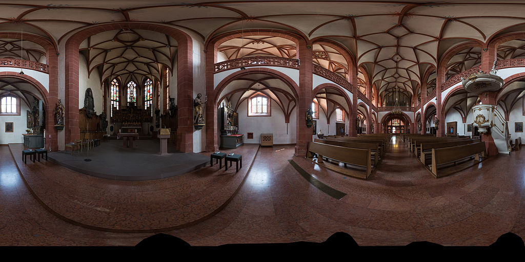
The result is something that looks a bit like a reflection of the environment. It is not perfect because we're projecting a flat, single-viewpoint photograph onto a spherical environment. The proper method would be to take a panoramic photo from the location of the CG object, using either manual stitching of several photos shot in different directions or a panoramic camera, such as the Ricoh Theta.
Depending on how much accuracy you need, you could try to find a panorama that roughly matches your environment and use that as your reflection color map. If you're really ambitious, you could even kit-bash something using photos from multiple sources to try to create a reflection environment. Such a synthetic environment map should be in a lat long projection, which looks like one of those maps of the world where Antarctica and the northern parts of Canada and Russia are stretched way out.
Now that the shading is in a good state, you may want to adjust the intensity of the lights. There is no need to exactly match white and black levels to the plate—we can do that with a color corrector. Instead, just try to get the relative contrast of the cup to its own highlights looking about right. You might go back and forth between the light and the diffuse color a few times until you're satisfied.
Shadows
There are two different ways to get shadows into the scene. One is to use a camera projection to texture the CG table surface with the plate. The other is to create a separate shadow pass. As I mentioned in the chapter on multi-pass CG compositing, the term "pass" is overloaded with meanings. Some people will use it to mean simply the shadow component that has been saved separately from the main beauty render. In this case, I am using it in a slightly different sense: A separate render with special settings that gets us just the shadows and nothing else.
In order to get only shadows, we'll need to create some overrides for the geometry and materials. First, let's duplicate the Renderer by Copy-and-paste and connect it to the Merge3D, just like the first Renderer. Hit F2 to rename it to "Shadow_render" so you remember what it's doing. Put Shadow_render somewhere with a little bit of space around it, but still convenient to your main Flow.
 We'll need two new nodes for this trick: An Override 3D and a Replace Material 3D. Make one of each and insert them into the Flow between the Merge3D and Shadow_render. The order doesn't matter.
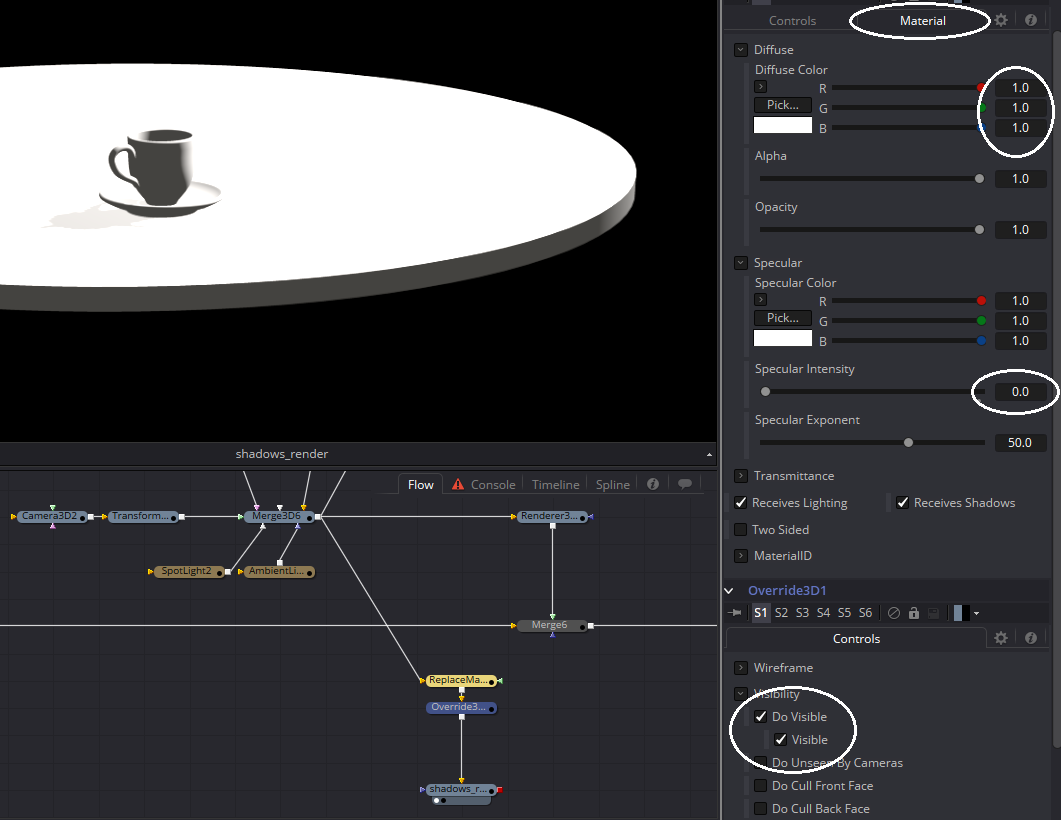
In the Replace Material 3D, switch to the Material tab and make sure that the Diffuse color is white—1.0 in all three channels. Set Specular Intensity to 0. Now every material in the scene has been converted to a matte white. In the Override 3D, check "Do Visible." The "Visible" checkbox will appear. It's probably already checked, but if it isn't, check it. That makes the table surface visible once more, but only for tools downstream. That is, it affects only Shadow_render, not the original Renderer.
Now, that shadow is rather thin. Let's do something about that. Select the SpotLight and twirl down its Shadow controls. The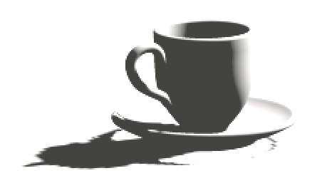 default Shadow Density is 0.5, which is why the shadow isn't very solid. Turn that all the way to 1.0. Now we can see that the shadow's quality isn't really very good; the edges are all jaggy, and there's probably at least one big hole in it. The shadow quality can be improved using the Shadow Map Size control. I found a value of around 4200 was adequate.
Now we have a pretty nice shadow, but it's razor-sharp. It would look great on the moon, but in an atmosphere shadows are more diffuse. In fact, looking at the plate, the shadows are very diffused. We need to blur the shadow. If you start playing with the shadow softness parameters, you'll probably notice that absolutely nothing happens. It doesn't seem possible to control the softness! Well, that's a limitation of the OpenGL renderer. Although it provides quite a bit of speed, some very nice supersampling features, and cool stuff like depth of field, the OpenGL renderer can't do soft shadows.
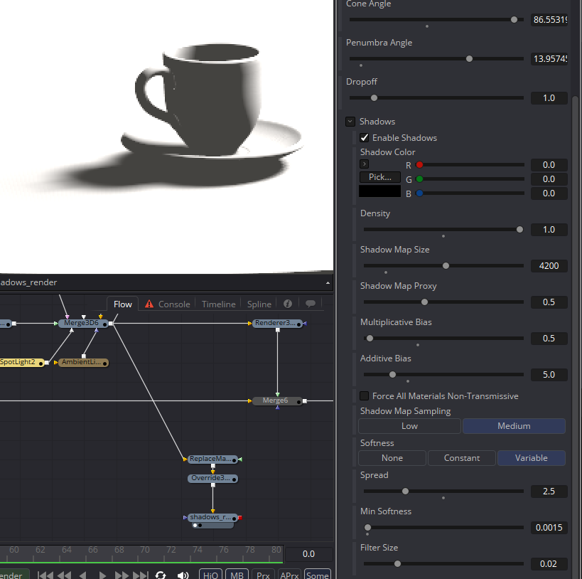 Upon switching the Shadow_render to Software mode, though, that big hole in the saucer's shadow comes back, and it turns all jaggy again. Fear not! Simply setting Softness to Variable fixes the quality. To fix the hole, we'll need to adjust the Bias control. Shadow biasing is a way to correct inaccuracies that arise from having surfaces that are very close together. The Fusion Tool Reference document has more information in the SpotLight 3D section (note, however, that the manual hasn't been updated to reflect newer softness control sliders). Adjust the Multiplicative Bias downward until most of the hole is filled in. I found a value of 0.5 to be sufficient. There is probably a tiny bit of a hole left, so use the Additive Bias to fine-tune until it goes away. Mine settled at around 5.0.
At this point, the shadow is filled in, but it's likely too soft. Reduce the Spread until the blurriness of the shadow about matches what you see cast by the planter in the plate. If you want to soften the sunward side of the shadow, a very small value in Min Softness can do that. As you can see from my screenshot, I used 0.0015. The Filter Size control adjusts the with of the pixel filtering algorithm that smooths the shadow edges. Turning it up will give a higher-quality result, but the shadow will blur even further. Usually it only needs to be changed if you get flickering in the edges of your shadows.
We now have a decent shadow pass, ready to apply to the plate. There are two possibilities: A Merge with a Multiply Apply Mode is one possibility. The other is to put the shadow pass into a Bitmap node, which converts it into a mask. If you use the Merge method, you'll probably need to use a BrightnessContrast node set to Clip White in order to prevent superwhite pixels in the render from increasing the brightness of the table. I prefer the masking method because it makes it easy to tint the shadow to match the plate. So that's the route I'll walk you through.
Create a Bitmap node and connect it to the output of Shadow_render. In the Bitmap's control panel, set the Channel to Luminance. Create a Color Correct and insert it right before the Merge that combines the cup with the plate. Plug the Bitmap into the Effect Mask (blue) input of the Color Correct and adjust the Gain downward to create the shadow. In the screenshot, you can see a problem: The bitmap mask created from the render is darkening everything that isn't covered by the table surface's geometry. We can fix that by using that Ellipse mask that is probably still connected to the Merge node. Adjust its size and shape so that it contains only the shadow, and plug it into the Effect Mask input on the Bitmap itself.
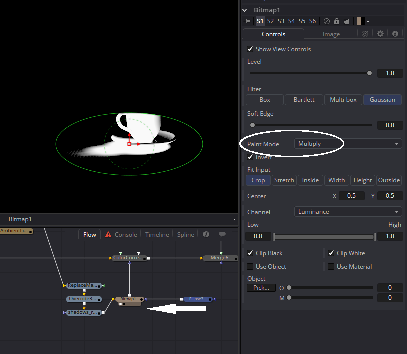 Things will immediately go completely wrong, but fixing it is as simple as changing the mode used to combine the two masks. In the Bitmap node, change the Paint Mode to Multiply. Now, the black pixels created by the Ellipse zero out the white pixels everywhere outside its borders.
Now we just need a bit more contact shadow to really sell it. Rather than trying to get anything more out of the 3D, though, it is simplest to just use a softened Ellipse to mask another Color Correct.
Reflection, Part Deux
Almost done! There is just one last detail to squeeze out of the 3D system. I'd really like to see the cup reflected in the surface of the table. To make that happen, let's look at how a reflection works:
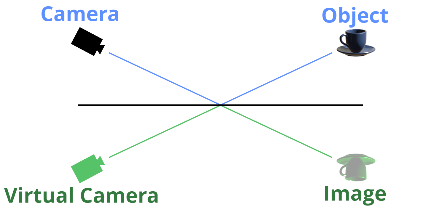
A light ray that travels from an object, reflects from a surface, then enters the camera's lens creates an image of that object that appears to be the same distance behind the surface as the object is in front of it. If we were to flip ourselves into that reflection world, we could likewise assume that a ray that travels from our image, hits the backside of the surface, and enters the lens of a virtual camera would create another image exactly superimposed on the real object. That is, the object becomes its own reflection when photographed by a camera on the other side of the surface.
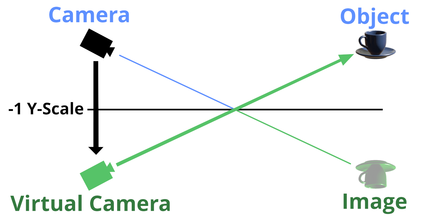
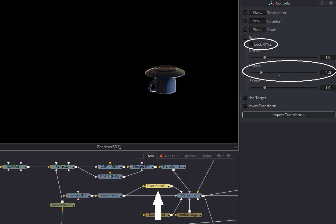
This property means that the fact that we never moved the table's surface away from 0,0,0 helps us to create a reflection camera with ease. Simply create a Transform3D, uncheck the Lock X/Y/Z Scale box, and enter -1.0 in the Y Scale field. Connect the output of the Camera (and any attendant Transform3Ds you may have added to it) to the input of the new Transform3D, and pipe the output of the Transform into the Merge.
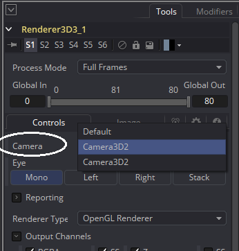
 The existing Renderers will not be disturbed by the addition of a second Camera, but you can duplicate the main renderer and set it to use the second Camera3D to get a reflected image of the cup.
Since we're actually using the same Camera3D node for both the normal and the reflected image, it may not be clear which one is which. In a more complicated scene with several cameras, it might be better to instance the camera instead of just branching it.
 The reflected image should be Merged onto the plate before the shadows. Depending on the height of the Cylinder you used for the table surface, it may be necessary to translate it upward so that the bottoms of the saucers meet.
Use the Blend control in the Merge to reduce the reflection's opacity until it looks about right. Add some Blur, and maybe a Displace to it to simulate the uneven surface of the wood. Reflections are also often less saturated and tinted by the reflecting surface, so a Color Corrector could also help it settle in.
Add a Logo
I was just about to be done with this thing, but then I decided why not add my logo to the cup? We didn't talk about texture maps or combination materials yet, so, as my friend Vito says, we can go FURTHER!
First, select an appropriate logo to put on the cup. It should be a single color (black and white) image of reasonably high resolution. Although the logo will be quite small in the finished image, you might need to do some transformations on it, and higher pixel counts hold up better. Mine is 1488 x 402.
Textures work best when they're square, so make a Background and set its color to black with 0 alpha. Switch to the Image tab. Set the Width and Height to the same value, both bigger than the biggest dimension of your logo. Most graphics programs are most efficient when texture resolution is a power of 2, so I set mine to 2048×2048. Merge the logo onto the Background. The technique I'm going to use will work best if the image is white on transparent, so do whatever you need to do in order to make that happen.
We'll want to be able to move the texture around on the cup, so create a Texture2D node and feed the image into it. Now, I want my logo printed on the cup in gold leaf. The best Material for metallic surfaces is the Cook Torrance Material, which uses a Roughness slider to control specularity. Make a Cook Torrance and connect the Texture2D node to its DiffuseColorMaterial input (gold). If you put the shader into the Viewer, you should see a shader ball that is mostly black except for your white logo. We could color correct the logo to get the gold color we're after, but it's simpler to just use the Diffuse Color controls in the material itself. This color will be multiplied by the texture. Since the texture is just black and white, the result will be a logo in the color that you choose here.
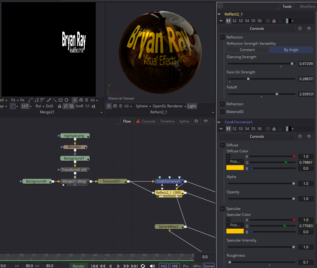 Once you're satisfied with the Diffuse Color (mine is 1.0, 0.8, 0.0), set the Specular color to be exactly the same, and pull the Roughness all the way down to 0.1. Metals tint reflections with their own color, so we want the specularity to also be yellow. Add a new Reflect node, but this time set the Face On Strength at 0.3 or so to make the gold leaf shinier than the rest of the cup. As before, plug the SphereMap into the ReflectionColorMaterial input and the Cook Torrance into the BackgroundMaterial.
Now I need to do a little bit of trickery to properly combine this new material with the existing one. First, I'll knock out all the reflections everywhere except inside the logo. Use a ChannelBoolean node, but this time we'll use the 3D version. When you use the Ctrl+Space dialog to make a Boolean, you may have noticed that there are two: ChannelBoolean (3Bol) and Channel Booleans (Bol). We want the 3Bol version. Operand A can be left alone. In each Operation slot, change the formula to A * B. In Operand B, set each slot to Alpha FG. Now, each Background channel will be multiplied by the Foreground's alpha, resulting in a 3D stencil of the logo:
![]()
This stencil can now be added to the existing material with another Channel Boolean. Between the original Reflect node—the one that currently feeds both the Cup and the Dish meshes—and the Cup, insert the new Channel Boolean. Connect the Boolean you just finished setting up to the Foreground input. Now Set the Operation of the RGB slots to A + B. Leave the Alpha slot alone.
The very last step we need to perform is to create new UVs on the Cup. It already has some, but they're not laid out in any sensible fashion. Instead of trying to distort the texture to fit the strange UVs, we'll just overwrite them with a UVMap3D node. Place this new node immediately after the Cup FBX node and set the Map Mode to Cylindrical. If you put the UVMap node into the Viewer, you'll probably see your logo dramatically squashed into a line in the middle of the cup. We need to scale the UVs in the Y direction until the proportions look correct. For me, that was a value of about 70.
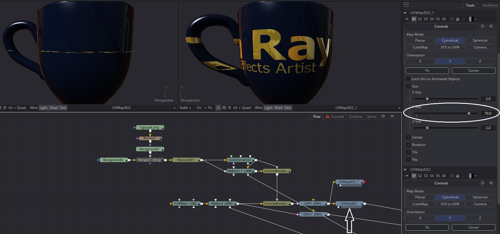
Finally, to scale and move the logo to exactly where we want it to go, we can use the controls in the Texture2D node. Once you have the logo in approximately the right place, take a look at your finished comp to be sure you can see it.
![]()
2d Integration
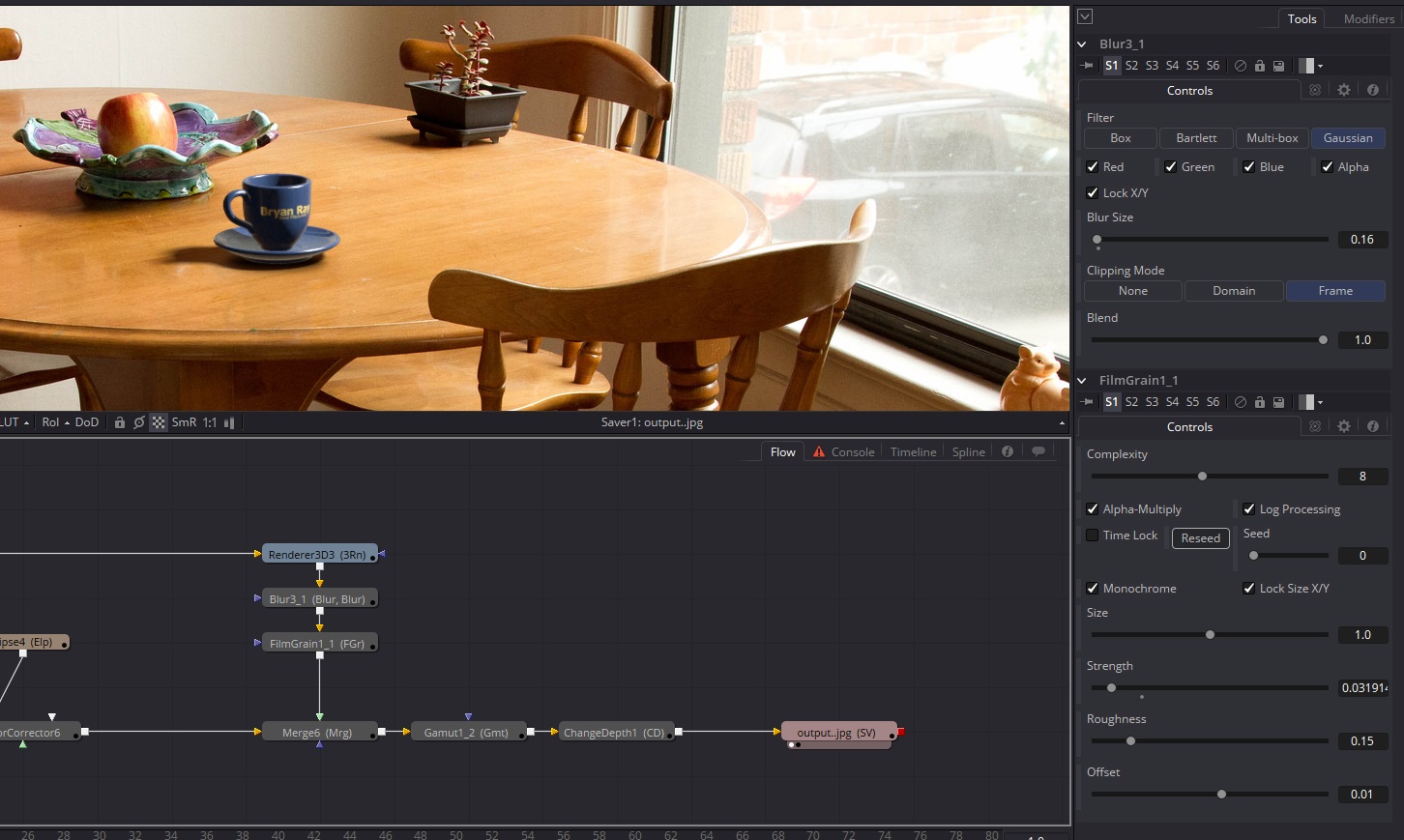
Once all of the 3D work is done, it's time to tune the composite using 2D tools. Blur it subtly to match the plate's level of sharpness. Add a very small amount of FilmGrain to match the noise from the camera's sensor and the jpeg compression. Finally, convert it back to sRGB with a Gamut node and export to the format of your choice.
Whew! That was a long one, and we barely scratched the surface of Fusion's powerful 3D system! Although 3D in a compositor isn't nearly as robust as a dedicated application such as Houdini, hopefully you can see how useful it is to have the ability to do minor 3D tasks here in the compositor, saving the 3D artists' time for more complex effects.
Next time out we'll get into some more technical aspects of compositing with a study of cameras, lenses, and sensors and some techniques for matching the flaws they produce.
small 'wordo', as it were, in para 11: 'climate' should be 'client' is suspect!
"Generally speaking, you want to give the image back to your climate in the same condition as you received it"
mind you, in these very strange political times, it is perhaps not bad to remind people that we ought to try to preserve the climate in the same condition we found it!
Ha! Thanks. Wish I could blame auto-correct for that, but I didn't write this 7000 word article on my phone, so I'm afraid that's all me!
Tried it and achieved the results in fact i used muse vfx logo on my cup 😁
thank you Bryan for the detailed information 😃