Painting clean plates is another task commonly assigned to junior compositors. While roto is an easy and tedious job, paint can be very challenging. Every shot brings unique challenges, and many will require you to use a variety of techniques. A shot might require paint work in order to remove wires or other rigs that were necessary for the shot but shouldn’t appear in the finished work. Sometimes lighting or sound equipment is visible accidentally and needs to be removed, or it was impossible to shoot a fantasy piece in the countryside without telephone wires visible in the background. Perhaps an effect calls for a character to dissolve into mist, and you need to create whatever set should have been behind them.
Although I use the term “paint,” the Paint tool is usually not the first tool I reach for when doing this kind of work. If you attempt to touch up an image frame-by-frame by painting on it, you will almost certainly introduce chatter—pixels that dance and flicker—because it is virtually impossible to repeat a paint stroke from frame to frame, particularly if the image being painted is also moving. Transforms, warps, image filtering, and other methods are all used to supplement the Paint tool when the time comes to remove something from the frame. Let’s get to work.
Since the techniques I will demonstrate this time are very specific to this footage, I encourage you to go ahead and follow along with my plate rather than using your own at first. Download the footage here: 005_paint_plate.zip (55.3 MB)
Wire Removal
The first thing to do when you’ve been assigned any shot is to load it up and play it a few times to get a sense of what you’ll need to do. In this shot, we’re going to remove the single telephone line in the middle of the frame and the four drops of water on the left side of the lens. The wire is the easiest thing to address, so we’ll start with that. But first, let’s change the comp’s Preferences so that we don’t have the same resolution mismatch problems we had in the Tracking chapter.
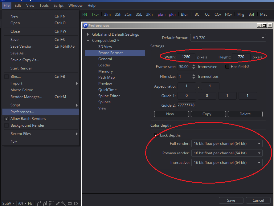 File > Preferences will call up the Preferences window. There are two sets of Prefs to be aware of: The Composition’s settings and the Global settings. The Composition settings should already be twirled down. Find the Frame Format panel and change the Width and Height settings to 1280 x 720 to match the plate. While we’re here, let’s also change the color depth to 16-bit Float per channel (64 bit). This gives us a lot more latitude in color correction and filtering, letting us make changes without losing as much quality. 16-bit is generally enough precision for most tasks. See the Anatomy of an Image appendix for more details on that topic. Save the Preferences and select the Loader with the footage in it. On the Import tab, change “Format” to “Default” to force the image stream into the 16-bit mode you chose in the Preferences.
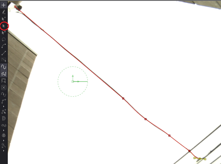 Set your playhead to frame 41, where you can see the entire wire. This is the best place to start because you can make a matte that will cover the entire thing. The last time we used the Polygon tool, we used it to make a closed shape. This time, we’ll leave the shape open and give the spline some thickness to cover the wire. Make your Polygon and start drawing a spline over the wire. It doesn’t need to get every subtle bend; approximate is good enough. In the screenshot, I have circled an important button in a toolbar that appears only when you have a spline tool selected. This button changes the manipulation mode to “Modify Only,” which prevents Fusion from adding any additional points to the spline. Activating it will allow you to move the spline’s points without it trying to close the shape or add more vertices (the plural form of vertex, which is a point that helps to define a shape in computer graphics).
In order to be able to see the matte created by the spline superimposed on the image, we need to Merge it onto the plate. You could plug the spline directly into the Foreground input on the Merge, but the spline will be white, and the sky is also white, so you will have a hard time seeing it. Instead, make a Background node. The Background, unlike most Fusion nodes, does not have a Background input of its own. It is the equivalent of a Solid in After Effects or a Constant in Nuke—in its default configuration, it outputs a single color to every pixel. Fusion’s Background has a few other modes too, enabling it to also make various kinds of ramp (also known as a gradient, a ramp varies the color of a pixel depending on its position.) The Background does have a Mask input, though; plug your Polygon into that, then put the Background node into the Foreground of the Merge and view the result in your Viewer.
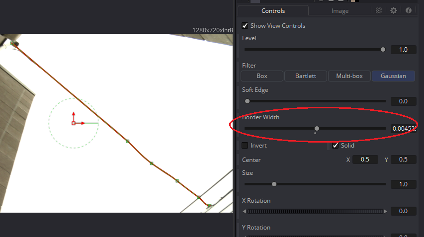 At first you won’t see anything because the spline still doesn’t have any thickness. Select the Polygon tool and increase the Border Width. This is another slider that benefits from the finer control offered by holding Control while moving it. You need just enough thickness to completely cover the wire. Don’t worry about the connectors at the ends; we’ll address those separately. I’ve made my Background red to make it easy to distinguish the spline from both the wire and the sky.
Now put those Rotoscoping skills to good use, and keep that wire covered through the whole sequence. Once again, try to move the entire spline at once, holding the T and S buttons to Twist and Scale. Don’t go overboard trying to make it perfect; there will be plenty of time to touch it up once we see how well it’s working.
Once you’re done animating the spline, add a Transform node after the footage (not the Merge—we don’t need that in the actual composite), put it in the Viewer, and connect the Polygon to the Mask input. Right click the Center control in the Poly’s control panel and choose Animate to set a keyframe. Now move the handle in the Viewer. Since the Polygon is masking the Transform’s effect, only the area containing the wire moves. And since most of the wire is surrounded by pure white sky, the wire vanishes, being covered by the sky around it.
Now, notice that the place where the wire crossed another wire has a little discontinuity:
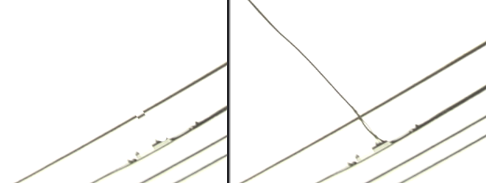
Adjust the Transform a little bit to pull that bit of the wire neatly into the hole. Then go through the sequence, adjusting it so that the hole remains filled the entire time. There may still be a little bit of a visual artifact near the edges of the mask. Use the Polygon’s Soft Edge to smooth it out. Using Soft Edge might reveal a little bit of the wire again, so counter that effect by increasing the Border Width a little bit more. Play through the sequence, looking for anywhere that your roto isn’t quite accurate enough and make whatever adjustments to the Polygon that you need to in order to cover them up.
You will probably have some holes in the sky now near the edges of the frame. Another mask to isolate them and another Transform right after the first can fill those in. Let’s move on to the water: a much more difficult problem.
The Clean Patch
The cinematographer neglected to wipe off the lens for this shot, and there are four raindrops marring the image. While the camera is still, they’re not much of a problem, but as soon as it moves, the refraction becomes very distracting.
The usual method to address a problem of this sort is to create a clean patch, a single frame of the wall without the blemish. If a frame can be found that shows the entire portion of the wall that needs to be painted but that does not show evidence of the drop, we could use that frame to cover all the others. Starting with the lowest drop, I see a couple of frames that are possibilities, but none of them contain all of the pixels I’ll need. Therefore, the clean patch will need to be composed of at least two frames. It is best to try to find frames with the least amount of motion blur possible. Frames 30, 36, and 46 seem like good candidates. Between the three frames, we should be able to reconstruct all of the wall that is facing us.
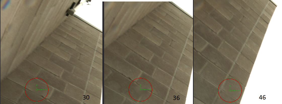
The Ellipse indicates the location of the raindrop, which is much easier to see when the clip is in motion.
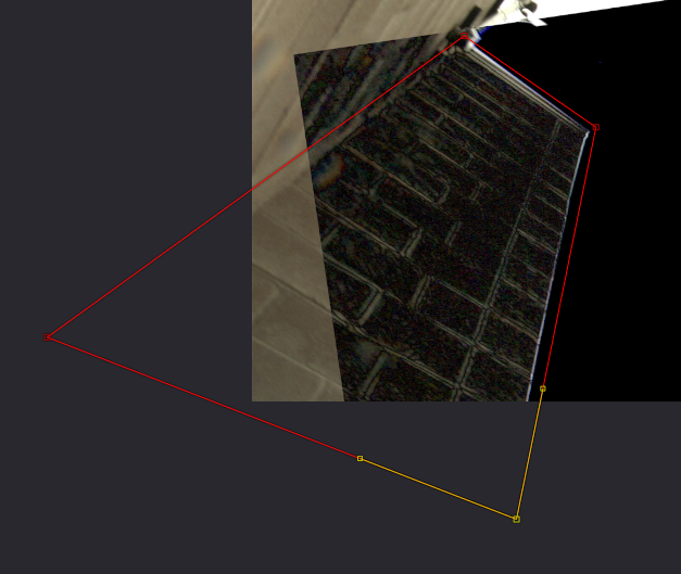
We want to make a single, large patch that can be tracked in over the wall through the entire sequence to hide the drops. No single frame contains all of the pixels we need. In frame 30, the lower part of the wall isn’t visible. By the time we get to 46, the camera left part of the wall has passed off-screen. In order to make this patch, then we’re going to need to be able to get pieces from three different frames at the same time. For that, we call upon the Time Stretcher tool.
TimeStretcher is a very useful tool that can be used to pick which frame we want to see at any given time. By default, it comes in with its Source Time control already animated. We only need it to give us one frame, though, so right-click the control and choose Remove TimeStretcher1SourceTime. The numeric field goes from green to dark grey to indicate that it is no longer animated. Change Source Time to 30 and plug the output of the last Transform into its input. Now, no matter what frame the playhead is on, the output of the TimeStretcher will always show frame 30.
Make two more TimeStretchers and set them to frames 36 and 46. The next thing we need to do is to align all three frames to one another so that when we transfer pixels from one to another, everything will line up. Frame 36 has more of the wall visible than the other two, so I am going to use that as my base position.
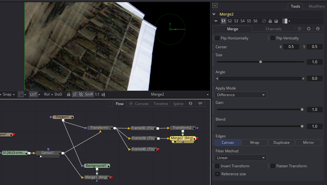
I have a Merge here with the Apply Mode set to Difference. In this mode, wherever the pixels of the Foreground and Background are the same, the image is black. The greater the difference between the two inputs, the brighter the composite becomes. This is a very useful way of lining up two frames from the same sequence. Just try to make the image as dark as you can. It’s unlikely you’ll get it to go completely black, but you should be able to get a decent alignment in this manner.
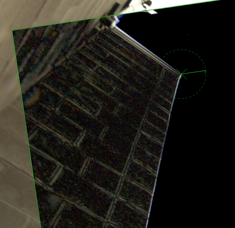 When I do the same procedure to line up frame 46, I can see that there is definitely a perspective shift in these frames. If I want them to line up better, I may have to do a little bit of warping.
Fusion’s Grid Warp is a powerful tool for altering perspective and distorting elements to match surfaces. It defaults to an 8 x 8 grid, which is too many points for this job. We have a nice rectangular surface and just need a perspective adjustment, so change the X and Y Grid Size both to 1. The grid of lines in the Viewport should have vanished, leaving just a green frame around the entire image.
There is a catch to using Grid Warp. Unlike Transform, Grid Warp discards pixels that are outside the visible frame. In order to ensure that we don’t accidentally lose pixels we will need later, I have added a Crop tool right after each TimeStretcher to increase the size of the canvas enough that none of the pixels will be lost. My first attempt at this cleanplate revealed that the problem area was the bottom of the frame, so I have increased the Height of the image to 1180. Turn on the “Keep Centered” switch to move the wall away from the bottom edge. You could also use the Y Offset control to accomplish the same thing, but keeping the crop centered sometimes makes it easier to undo the process later in the flow, so I customarily use it unless there is a reason not to.
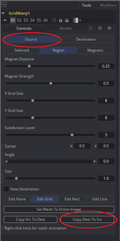 The Grid Warp has two components: The Source Grid, which holds the original shape of the element, and the Destination Grid, which holds the warped image. It would be nice if our grid points lined up with the edges of the building we were going to manipulate, but if we start moving them right now, we’ll be actually moving the pixels around. Switch to looking at the Source Grid by clicking the Source button at the top of the control panel.
All of the lines you just got rid of reappear because the Source and Destination Grids do not have to have the same resolution. You can change the resolution the same way you did before, or you can use the Copy Dest to Src button to automatically make the change. Moving the points while the tool is in this mode will not change the image until we go back to viewing the Destination.
 Another default setting that is not useful in this case is the Region Magnet Type. Change it to Selected so that you can easily grab a vertex and move it, just like a spline’s points. Keep the borders slightly outside the pixels you want to manipulate. Anything that falls outside of this box will be cut off.
Now click the Copy Src to Dest button to copy this shape to the Destination Grid and switch back to the Destination to start performing the warp.
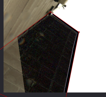
Adjust the points until the wall is as dark as you can make it. You can also adjust the Bezier handles to stretch or squash the pixels for a better match. Here’s how it looks after the warping (this screenshot was made before I knew I would need those crops):
Do the same process for frame 30 so that all three images are reasonably well aligned, then switch both Merge nodes’ Apply Modes back to Normal, and put the output of the first Merge into the background of the second, like so:
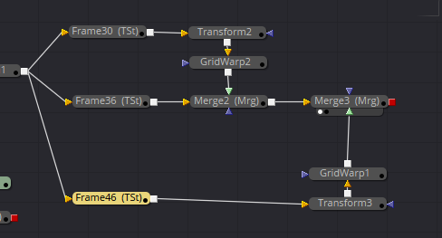
The chosen base plate goes on the bottom, and the two patches go on top of it. Next we need to choose which pixels we’re going to take from which frame to get rid of the raindrops. It’s easy to see at least one of the drops from Frame 46. To get rid of that one, we want to mask the Merge where it’s coming in—Merge3 in my flow. I am using an Ellipse node with its Invert switch toggled. It’s pretty easy to see the seam, so I turn the Soft Edge up to feather it out across a large area.
I do the same thing to cover the seam and raindrop near the bottom of the Frame 30 patch, plugging an inverted Ellipse into Merge2 and feathering it out. Once all that’s done, we need to extract just this wall to use as an element that will replace the original wall. For this task, I use a Polygon to contain all the pixels I intend to use. That goes into the Garbage Matte input on a Matte Control.
The Garbage Matte is a quick way to apply a mask to an image and premultiply it all at once. The default mode makes all the pixels inside the matte transparent, which obviously isn’t what we want here. You can invert the Polygon itself, or use the Invert Garbage Matte switch in the Matte Control.
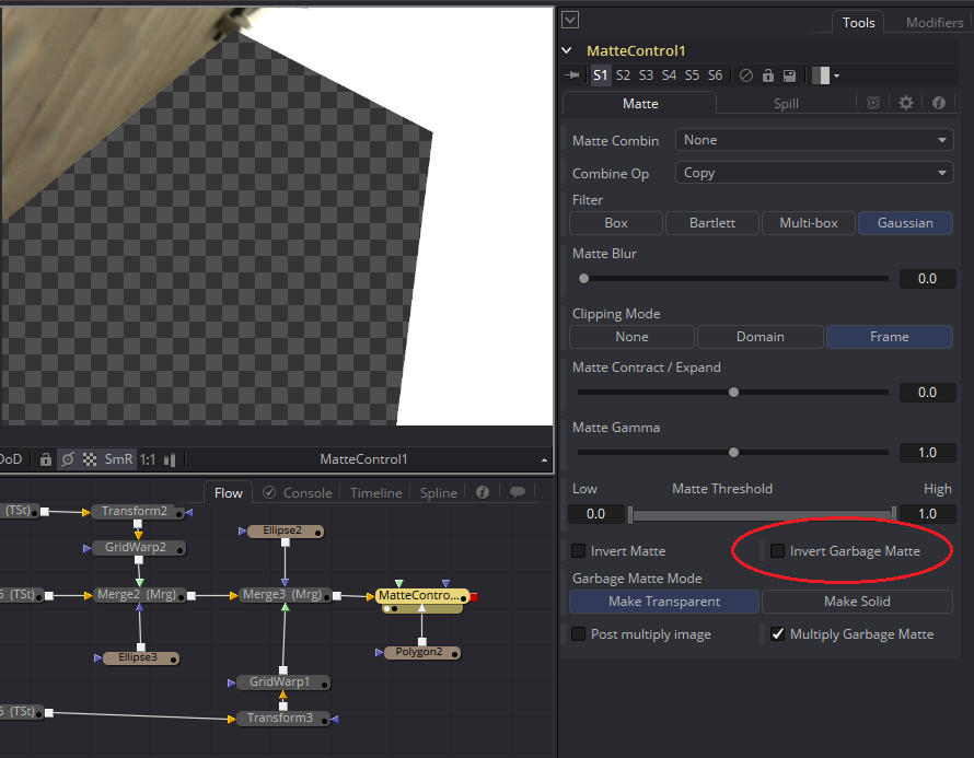
Remembering that the drops refract the edge of the building a few pixels away from the edge, I’ve made my Polygon larger than the wall itself. If there were any detail in the sky, that might not work, but since it’s just a flat white, there won’t be any visible mismatch from doing it this way.
We did all of that just to make a single frame element to cover what was originally photographed. Now we need to track it in over the original pixels. There’s a catch, though: We’ve compensated for a small perspective shift in building the clean patch, so we’re going to need to compensate for that same shift when the clean patch goes on. We’ve already used a Grid Warp to adjust the perspective once on a still frame. This time we’re going to animate it to change the perspective over time. First, though, we need a Tracker to get the rough motion. (If you have Mocha, this track would be much easier. I do not, so I will attempt to solve the motion using only Fusion’s point tracker.)
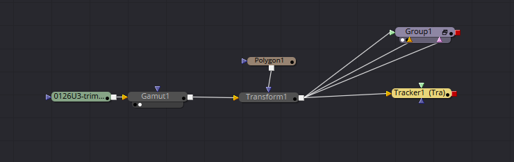
My flow’s gotten a bit messy during this process, so I’m going to do a little house cleaning to simplify it. First, I don’t need that Background and Merge I used to evaluate the roto of the wire, so I’ll delete those. I don’t need to look at all of those nodes that created the clean patch, so I’ll tuck them away in a Group. Select all the nodes, right-click, and select Group, or use the shortcut Ctrl+G. All of those tools will be collected into a single Group1 node. Since only the Matte Control has an unconnected output, that’s the tool that is connected to the Group’s output. You can still access the tools inside the group by expanding it with the little window icon on the right edge, but you won’t be able to connect anything from outside the Group to them unless you Ungroup it first.
Here I have added the Tracker node. In the Tracking chapter, I mentioned that the Tracker works best in sRGB space, but in this case I haven’t changed the color space before tracking. This plate is bright enough that Fusion shouldn’t have any difficulty matching the pattern. Naturally, Fusion makes a liar out of me as soon as I try it.
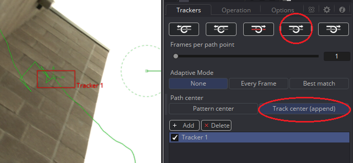
This kink in the tracked path indicates where the Tracker failed. I have positioned my playhead on that frame and adjusted the pattern box to a different shape, hoping that a slightly different pattern will be better. Since I had to move the pattern box back into position and couldn’t be sure I put it in the exact spot it needed to go, I have also set it to Track center (append). This mode lets you perform an offset track. You can move the pattern box to a different group of pixels, but the tracked point will continue from its original location. It’s handy for times when the point you’re tracking wanders off the edge of the screen, as will happen in this shot at around frame 60.
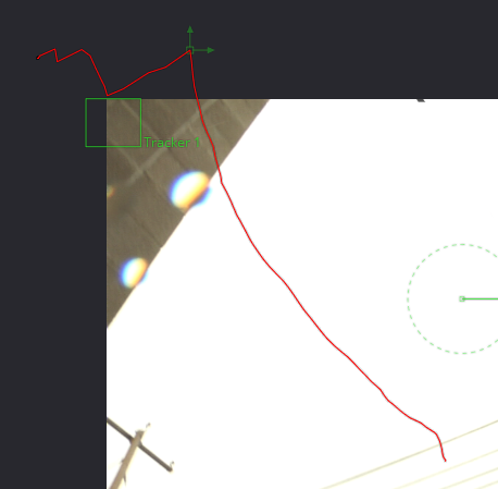
Since I have to restart the Tracker in the middle of the sequence, this time I will use the “Track forward from current time” button. This time, my track stays reasonably solid until frame 61, at which point it goes nuts again. With Track center (append) still selected, all I have to do is move the pattern box to the edge of the building and start up the track again. It’s important to choose a pattern that is about the same distance from the camera as the tracked point so that the perspective change doesn’t influence the motion too much.
My new pattern takes the motion to only frame 66. At this point, I don’t think there is much hope that the tracker will help me any further. I’ll have to go the rest of the way manually. Looking at this tracked path, I wonder if I can extend that arc a few more frames by using the Spline View?
As you did in the Tracking chapter, right-click in the Viewer, choose the tracked path Polyline, and click “Convert to XYPath.” Then switch to the Spline View and check the box next to Tracker1/Tracked Center 1/X.
If we assume that the rough arc described by the existing keyframes continues until the wall leaves frame, then we might be able to estimate its motion simply by adjusting this graph.
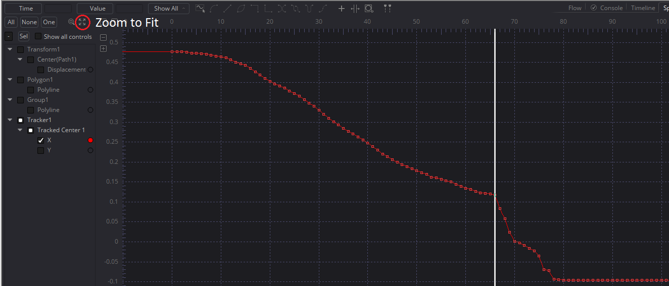
Start by deleting all but one of the keyframes after the point where the track broke down. Use the Bezier handles of the last valid key and the one left over after deleting to try to continue the curve. Do the same thing with the Y keyframes.

I honestly have no idea if this will work. Let’s try it out!
First, we need to compensate for changing the resolution of the clean patch. Merging it on top of a black Background with 0 Alpha reformats it to our Default frame format while preserving any pixels that fall outside the new canvas.
Put your playhead at the beginning of the timeline. The Tracker references its motion based on one of the end points of the tracking data. Obviously, the last frame is probably bogus, so we should line things up here at the beginning. Plug the output of the Group into the Foreground of the Tracker. This time, we’ll use the Tracker’s internal Merge by setting the Operation to Match Move and the Merge to FG over BG. Just like we did to create the clean patch, set the Apply Mode to Difference.
Now we’ll use a Grid Warp to put the clean patch in its place. Set it up just like you did before, taking care to keep the lines of the grid outside the pixels you intend to warp. Don’t forget to copy the Source to the Destination Grid so that your starting position is unchanged and then switch to Destination mode.
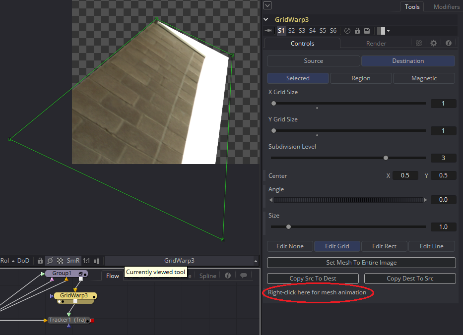
At the bottom of the Grid Warp’s control panel is a line that says “Right-click here for mesh animation.” Do so, and choose Animate. A small green line appears next to that text to indicate that there is now a keyframe.
Put the Tracker back into the Viewer and start moving the Grid Warp points until, as before, the wall turns mostly black. As with rotoscoping, it’s usually a good idea to select all the points and move them together at first. The (T)wist and (S)cale shortcuts work just like they do for splines.
Once you have the wall lined up at the first frame, move forward to see how the track is working. It will quickly shift out of the proper perspective, but don’t try to correct it too often. Scoot up to one of your source frames (I used 36) and set a keyframe there by warping the wall into place. Play the clip backward and notice how the Grid Warp interpolates between the two warp shapes, keeping the wall roughly the right shape. I found it necessary to add a few keyframes closer together near frame 70, where the camera’s rotation threw off the perspective quite a bit. From there on to the end, though, the extrapolated Tracker curves took care of things nicely.
Switch the Tracker’s Apply Mode back to Normal to see the actual pixels. They’re probably very blurry due to all of the warping and transforming we’ve done. I usually add an Unsharp Mask tool to sharpen things up after this kind of work. It still won’t be an acceptable level of quality, though, so we’re going to add some masks so that we can limit the quality loss as much as possible.
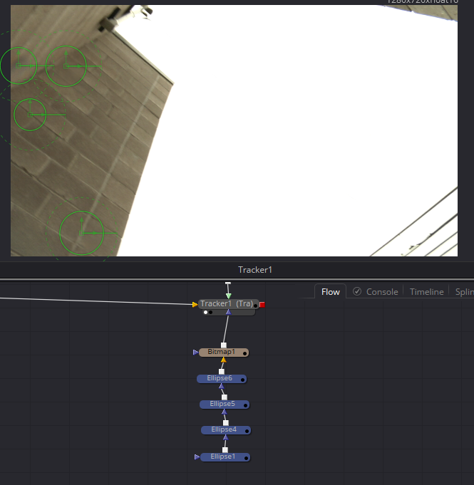 Fortunately, the water drops are stationary with respect to the lens, so rotoscoping them is easy. I dropped four Ellipses into the flow and arranged them to cover the rain drops. You can feather a whole stack of mask tools at once by putting a Bitmap node at the end of the chain and using its Softness control to blur all of them. I have done so here in order to blend away the sharp edges. The output of the Bitmap goes into the Effect Mask input of the Tracker.
Once that is done, play through the sequence again to make sure everything is holding up. I had to make a few small adjustments to the animated Grid Warp, especially as the drops hit the edge of the wall. There are also a few places in the sky where the drops are still visible, so I will use a Paint node to touch those up.
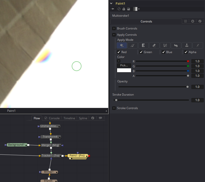 The Paint tool has a lot of options in it. In this case, I am going to start by leaving its default settings, which allow me to paint white one frame at a time. You can change the paint color by manually adjusting the color sliders or using the Pick button to sample colors from the footage. Clicking the button calls up a menu with the kind of color picker you might be familiar with from Illustrator or Photoshop. Just below the Basic colors grid is a button that says “Pick Screen Color” (new in Fusion 8). Clicking that button activates a crosshair cursor that you can use to choose a pixel from anywhere on your screen, even from another program, as your new paint color.
There’s a shortcut for this functionality if you only need a color from the Viewer: if you instead drag the Pick button onto the viewport, you will get an eyedropper cursor. As soon as you release the mouse button, the pixel under the eyedropper will be set as your paint color. The problem with selecting just a single pixel, though, is that there is a risk that noise will give you a color that is either too bright or too dark. You can instead select a region of colors by holding down Ctrl and dragging out a marquee around a group of pixels before you release the mouse button. The color in your paint tool will be the average of that group of pixels.
 Curiously, once you have made an averaged selection in this fashion, the Color Inspector Sub-View will use the same sample size. The 18×14 below the color swatch shows that my sampling area is 18 pixels wide by 14 pixels high.
In this case, though, white will do just fine, so I reset the color to white and start painting. Painting requires a steady hand and patience. I recommend using a stylus and tablet. Fusion can make use of pressure sensitivity, but it doesn’t respond to stylus angle or rotation if you have a tablet that has those features. Control-click and drag changes the size of the brush, or you can spin down the Brush Controls to use a slider to choose the size.
A paint stroke has a duration of only one frame, so you need to paint out the drops on each frame where they’re visible against the sky. That’s just 12 frames in my comp—it may be more or less in yours, depending on where the borders of your Grid Warps fell—so it’s not too onerous. I took the opportunity while I was at it to also touch up a couple of frames where I noticed that the wire was still visible.
I have a small problem near the bottom of my clean patch. The patch did not quite cover all the area I needed it to, so there are a few frames where the drop peeks out beneath it. I don’t want to go back into all of the warping and tracking, so I’ll fix these few frames with the Clone mode.
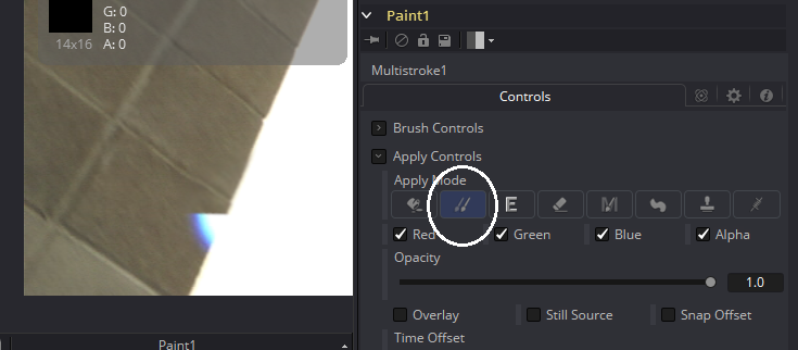
Cloning copies pixels from one part of the image to another. It is useful when you need to paint over a subtle gradient or a relatively uniform texture. First, set the spot from which you want to take pixels by alt-clicking. I recommend something a little below the drop and right on the edge of the building. Carefully start painting, starting right at the edge of the building inside the drop. The sample area will travel along with your brush, so you can paint in the texture of the wall along with the white of the sky. It may take a couple of attempts to get the sampling correct; it’s easy to make your stroke just slightly offset from where it should be.
You have to be careful with cloning not to create obviously repeating areas of pixels and not to sample from areas that don’t quite match the color and texture of the spot you’re fixing. Even a tiny change in light quality can create very obvious chatter once the clip is in motion.
There are a lot more options in the Paint tool. I recommend looking at the Fusion Tool Reference to learn what each button and mode does. You can clone from images other than the one in the background, set the stroke duration to greater than one frame, sample from frames other than the one you’re looking at, smear pixels together, and more.
Final Steps
As the camera move finishes, the water drops cross some of the telephone wires and the chain-link fence. Use the techniques you have learned so far to address those problems. It’s up to you whether you want to remove the wires entirely or try to paint them back in. The director won’t let you remove the fence, though—it has to stay in for continuity purposes.
The final challenge is graffiti and door at the beginning of the shot. You can use a technique similar to the one we used on the first wall, but that graffiti makes things a little tougher.
From there, it’s just clean-up. You will likely find some places where the techniques you’ve used break down a little, and you need to repair problems you’ve created. The upper end of the wire, for instance, overlaps with the light fixture, so you need to find a way to exclude it from the wire’s roto. There are also probably some artifacts at the edge of the frame where the wire was removed. Again, since the sky is pure white, it’s safe to just put a white patch over those spots and hand-animate it to stay put.
The very last step is to examine the sharpness and noise or grain characteristics of your work to ensure that it is integrated as well as possible. Be careful using sharpening tools; they operate by increasing the contrast between edges, and when applied too strongly, they cause an artifact known as ringing—pixels along already contrasty edges get too dark or too bright. Sometimes colors get too saturated in over-sharpened areas. Sometimes your patches might be too sharp, in which case a small blur might be needed. As for noise, the FilmGrain tool can match most noise profiles. I will talk more about noise and walk you through matching grain in the Cameras, Lenses and Sensors chapter.
Hi Bryan, I ran into an issue while doing some paint fix work while working in Resolve Fusion page, and can’t seem to find any answer on the web, wondering if you could help me out.
For example, I had to replace an actor’s hair and I asked my colleague to create the new hair portion in Photoshop and then bring it back into Fusion to comp it.
When working in Fusion, I tend to convert the camera colorspace (sLog3, ARRI Log) into DWG Linear or ACES Linear using the colorspace transform node.
After importing the still image I received from my colleague, which is only the portion of the hair with an alpha BG. After converting from Slog-3cine into Linear, the problem occurs, there’s a dark semi-transparent outline around the image and some negative RGB values around the edge.
This issue(negative values darken transparent edge) once occurred when I tried to plug a mask directly into the media-in (which is a video) and then do the colorspace transform. A friend of mine told me I could add an alpha-multiply node after my CST, plug the mask into the alpha-multiply node, and it worked out, no darkening edge, no negative RGB values, and all the soft edge parts showed up correctly.
But this time it didn’t work, with the still image with the alpha background. I’ve tried adding a bitmap as an effect mask to plug it into the alpha-multiply node, but there are still negative values and a dark semi-transparent outline in the picture causing artifacts.
I hope the description above was clear enough to give you a picture of what kind of problem I’m facing,
looking forward to your reply, thanks again for all the amazing content you’ve been putting out.
Probably you need to alpha divide before performing the color space conversion, then alpha multiply afterward. The problem is that many conversions, especially log-to-lin, assume broadcast-legal values, meaning “black” is defined as 7.5 IRE rather than 0. Anything below that value will become negative.
By dividing by alpha first, you remove the premultiplication that darkens the semi-transparent fringes, so they don’t get over-darkened by the color space transform, then you alpha multiply again to restore the correct edges. This should also take care of the negative values in the empty pixels because you’re multiplying by 0 in those areas. Many color correction and conversion nodes in Fusion have a convenient pre-divide/post-multiply switch that does this without needing extra nodes. Hope that helps!
Oh, and if video learning is easier for you, here’s one by Vito La Manna on the topic: https://www.youtube.com/watch?v=Q9c-uLcuVk8